460
BkLabel: NULL BkNextHop: FE80::7685:45FF:FEAD:102
Tunnel ID: Invalid Interface: Vlan-interface200
BkTunnel ID: Invalid BkInterface: Vlan-interface101
FtnIndex: 0x0 TrafficIndex: N/A
Connector: N/A
OSPFv3 IPsec profile configuration example
Network requirements
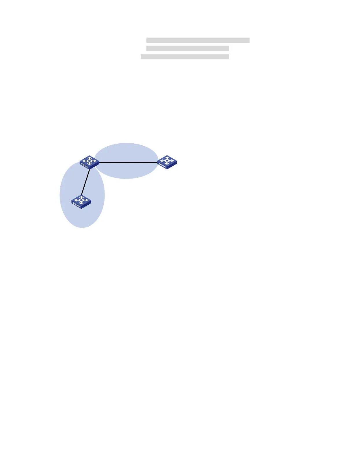
As shown in Figure 109, all switches run OSPFv3, and the AS is divided into two areas.
Configure IPsec profiles on the switches to authenticate and encrypt protocol packets.
Figure 109 Network diagram
Configuration procedure
1. Configure IPv6 addresses for interfaces. (Details not shown.)
2. Configure OSPFv3 basic features:
# On Switch A, enable OSPFv3 and specify the router ID as 1.1.1.1.
<SwitchA> system-view
[SwitchA] ospfv3 1
[SwitchA-ospfv3-1] router-id 1.1.1.1
[SwitchA-ospfv3-1] quit
[SwitchA] interface vlan-interface 200
[SwitchA-Vlan-interface200] ospfv3 1 area 1
[SwitchA-Vlan-interface200] quit
# On Switch B, enable OSPFv3 and specify the router ID as 2.2.2.2.
<SwitchB> system-view
[SwitchB] ospfv3 1
[SwitchB-ospfv3-1] router-id 2.2.2.2
[SwitchB-ospfv3-1] quit
[SwitchB] interface vlan-interface 100
[SwitchB-Vlan-interface100] ospfv3 1 area 0
[SwitchB-Vlan-interface100] quit
[SwitchB] interface vlan-interface 200
[SwitchB-Vlan-interface200] ospfv3 1 area 1
[SwitchB-Vlan-interface200] quit
# On Switch C, enable OSPFv3 and specify the router ID as 3.3.3.3.
OSPFv3
Area 0
OSPFv3
Area 1
Switch A
Vlan-int100
2001::2/64
Vlan-int100
2001::1/64
Vlan-int200
2001:1::2/64
Switch C
Switch B
Vlan-int200
2001:1::1/64

 Loading...


