407
Route Flags: A - Aging, S - Suppressed, G - Garbage-collect, D - Direct
O - Optimal, F - Flush to RIB
----------------------------------------------------------------
Peer FE80::20C:29FF:FECE:6277 on Vlan-interface200
Destination 2002::2/128,
via FE80::20C:29FF:FECE:6277, cost 2, tag 0, AOF, 24 secs
Destination 1200:1::/64,
via FE80::20C:29FF:FECE:6277, cost 1, tag 0, AOF, 24 secs
Local route
Destination 4004::4/128,
via ::, cost 0, tag 0, DOF
Destination 1400:1::/64,
via ::, cost 0, tag 0, DOF
The output shows the following when an active/standby switchover occurs on Switch S:
• The neighbor relationships and routing information on Switch A and Switch B have not
changed.
• The traffic from Switch A to Switch B has not been impacted.
Configuring RIPng FRR
Network requirements
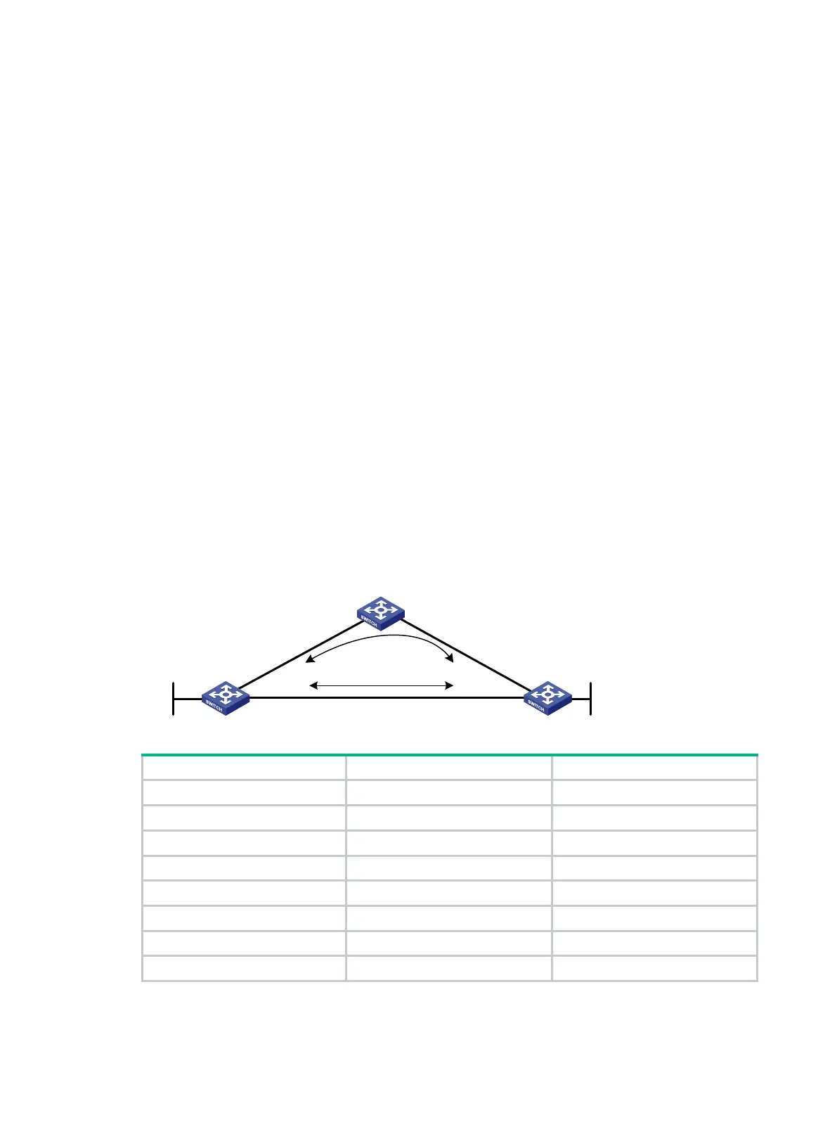
As shown in Figure 97, Switch A, Switch B, and Switch C run RIPng. Configure RIPng FRR so that
when Link A becomes unidirectional, traffic can be switched to Link B immediately.
Figure 97 Network diagram
Switch A VLAN-interface 100 1::1/64
Switch A VLAN-interface 200 2::1/64
Switch A Loopback 0 10::1/128
Switch B VLAN-interface 101 3::1/64
Switch B VLAN-interface 200 2::2/64
Switch B Loopback 0 20::1/128
Switch C VLAN-interface 100 1::2/64
Switch C VLAN-interface 101 3::2/64
Configuration procedure
1. Configure IPv6 addresses for interfaces on the switches. (Details not shown.)
Switch A Switch B
Switch C
Loop0
Vlan-int100
Vlan-int200
Vlan-int200
Vlan-int100
Vlan-int101
Vlan-int101
Loop0
Link A
Link B

 Loading...


