348
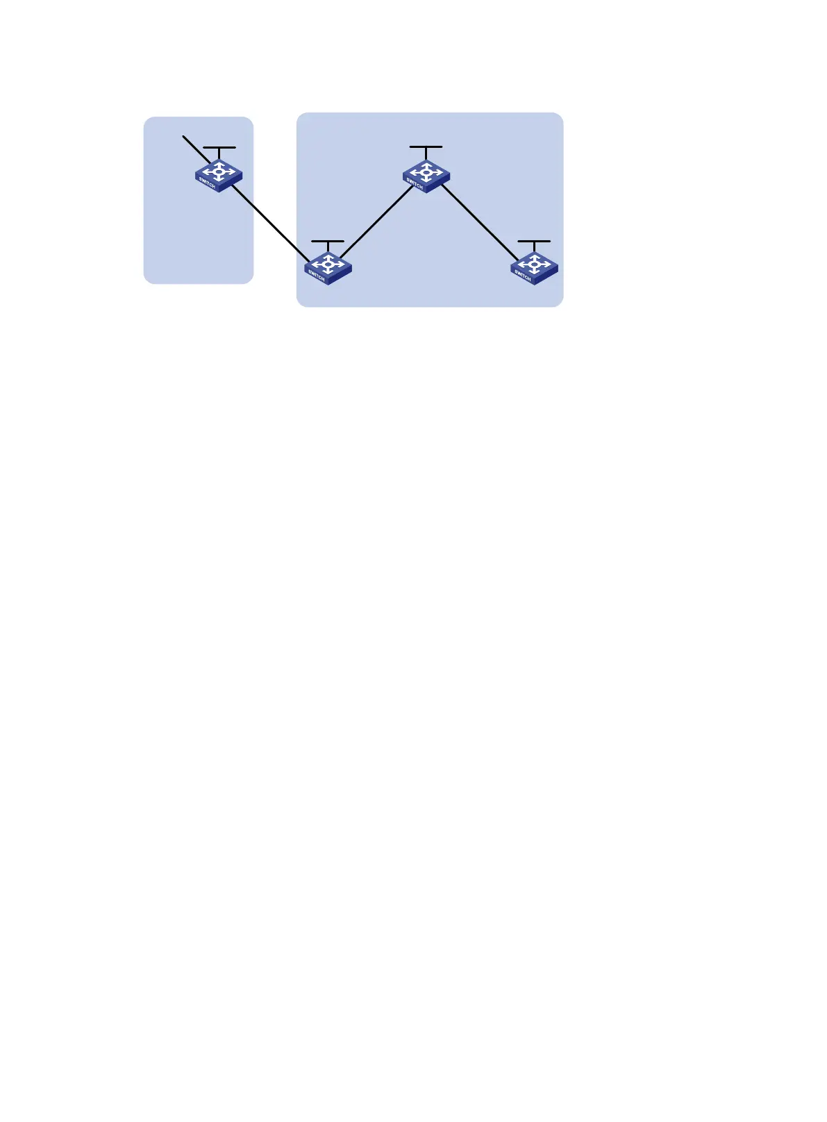
Figure 81 Network diagram
Configuration procedure
1. Configure IPv6 addresses for interfaces and IPv4 addresses for loopback interfaces. (Details
not shown.)
2. Configure IBGP and EBGP connections and advertise network routes through IPv6 BGP:
# Configure Switch A.
<SwitchA> system-view
[SwitchA] bgp 100
[SwitchA-bgp-default] router-id 1.1.1.1
[SwitchA-bgp-default] peer 100::2 as-number 200
[SwitchA-bgp-default] address-family ipv6
[SwitchA-bgp-default-ipv6] peer 100::2 enable
[SwitchA-bgp-default-ipv6] network 1:: 64
[SwitchA-bgp-default-ipv6] network 100:: 96
[SwitchA-bgp-default-ipv6] quit
[SwitchA-bgp-default] quit
# Configure Switch B.
<SwitchB> system-view
[SwitchB] bgp 200
[SwitchB-bgp-default] router-id 2.2.2.2
[SwitchB-bgp-default] peer 100::1 as-number 100
[SwitchB-bgp-default] peer 101::1 as-number 200
[SwitchB-bgp-default] address-family ipv6
[SwitchB-bgp-default-ipv6] peer 100::1 enable
[SwitchB-bgp-default-ipv6] peer 101::1 enable
[SwitchB-bgp-default-ipv6] peer 101::1 next-hop-local
[SwitchB-bgp-default-ipv6] network 100:: 96
[SwitchB-bgp-default-ipv6] network 101:: 96
[SwitchB-bgp-default-ipv6] quit
[SwitchB-bgp-default] quit
# Configure Switch C.
<SwitchC> system-view
[SwitchC] bgp 200
[SwitchC-bgp-default] router-id 3.3.3.3
[SwitchC-bgp-default] peer 101::2 as-number 200
[SwitchC-bgp-default] peer 102::2 as-number 200
Vlan-int100
100::1/96
Switch A
AS 100
Vlan-int100
100::2/96
Vlan-int101
101::2/96
Vlan-int102
102::2/96
Vlan-int102
102::1/96
Vlan-int101
101::1/96
Switch C
Switch B Switch D
AS 200
Vlan-int10
1::1/64
Loop0
2.2.2.2/32
Loop0
1.1.1.1/32
Loop0
3.3.3.3/32
Loop0
4.4.4.4/32

 Loading...


