374
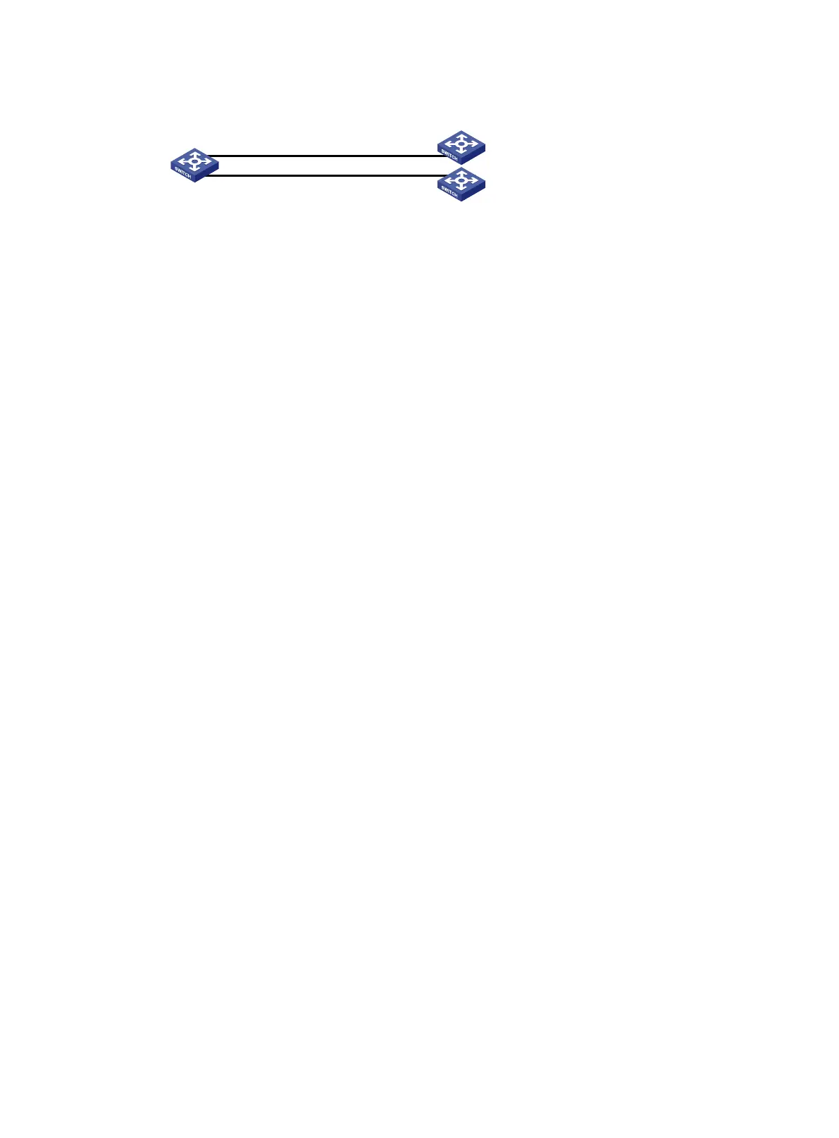
Figure 87 Network diagram
Configuration procedure
1. Configure Switch A:
# Create VLAN 10 and VLAN 20.
<SwitchA> system-view
[SwitchA] vlan 10
[SwitchA-vlan10] quit
[SwitchA] vlan 20
[SwitchA-vlan20] quit
# Configure the IP addresses of VLAN-interface 10 and VLAN-interface 20.
[SwitchA] interface vlan-interface 10
[SwitchA-Vlan-interface10] ip address 1.1.2.1 24
[SwitchA-Vlan-interface10] quit
[SwitchA] interface vlan-interface 20
[SwitchA-Vlan-interface20] ip address 1.1.3.1 24
[SwitchA-Vlan-interface20] quit
# Configure ACL 3101 to match TCP packets.
[SwitchA] acl advanced 3101
[SwitchA-acl-ipv4-adv-3101] rule permit tcp
[SwitchA-acl-ipv4-adv-3101] quit
# Configure Node 5 for the policy aaa to forward TCP packets to next hop 1.1.2.2.
[SwitchA] policy-based-route aaa permit node 5
[SwitchA-pbr-aaa-5] if-match acl 3101
[SwitchA-pbr-aaa-5] apply next-hop 1.1.2.2
[SwitchA-pbr-aaa-5] quit
# Configure local PBR by applying the policy aaa to Switch A.
[SwitchA] ip local policy-based-route aaa
2. Configure Switch B:
# Create VLAN 10.
<SwitchB> system-view
[SwitchB] vlan 10
[SwitchB-vlan10] quit
# Configure the IP address of VLAN-interface 10.
[SwitchB] interface vlan-interface 10
[SwitchB-Vlan-interface10] ip address 1.1.2.2 24
3. Configure Switch C:
# Create VLAN 20.
<SwitchC> system-view
[SwitchC] vlan 20
[SwitchC-vlan20] quit
Switch A
Switch B
Switch C
Vlan-int20
1.1.3.1/24
Vlan-int10
1.1.2.1/24
Vlan-int20
1.1.3.2/24
Vlan-int10
1.1.2.2/24

 Loading...


