441
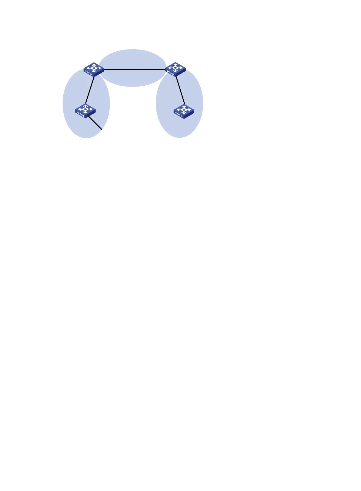
Figure 101 Network diagram
Configuration procedure
1. Configure IPv6 addresses for interfaces. (Details not shown.)
2. Configure basic OSPFv3 (see "OSPFv3 stub area configuration example").
3. Configure Area 1 as an NSSA area:
# Configure Switch A.
[SwitchA] ospfv3
[SwitchA-ospfv3-1] area 1
[SwitchA-ospfv3-1-area-0.0.0.1] nssa
[SwitchA-ospfv3-1-area-0.0.0.1] quit
[SwitchA-ospfv3-1] quit
# Configure Switch B.
[SwitchB] ospfv3
[SwitchB-ospfv3-1] area 1
[SwitchB-ospfv3-1-area-0.0.0.1] nssa
[SwitchB-ospfv3-1-area-0.0.0.1] quit
[SwitchB-ospfv3-1] quit
# Display OSPFv3 routing information on Switch A.
[SwitchA] display ospfv3 1 routing
OSPFv3 Process 1 with Router ID 1.1.1.1
-------------------------------------------------------------------------
I - Intra area route, E1 - Type 1 external route, N1 - Type 1 NSSA route
IA - Inter area route, E2 - Type 2 external route, N2 - Type 2 NSSA route
* - Selected route
*Destination: 2001::/64
Type : IA Cost : 2
NextHop : FE80::20C:29FF:FE74:59C6 Interface: Vlan200
AdvRouter : 2.2.2.2 Area : 0.0.0.1
Preference : 10
*Destination: 2001:1::/64
Type : I Cost : 1
Nexthop : :: Interface: Vlan200
OSPFv3
Area 0
OSPFv3
Area 1
OSPFv3
Area 2
Switch A
Vlan-int100
2001::2/64
Vlan-int100
2001::1/64
Vlan-int300
2001:3::1/64
Vlan-int200
2001:1::2/64
Switch C
Vlan-int400
2001:2::1/64
Vlan-int400
2001:2::2/64
Switch B
Vlan-int200
2001:1::1/64
Switch D

 Loading...


