3. Wiring
3.3 Wiring Method
3-43 ME0342-4B
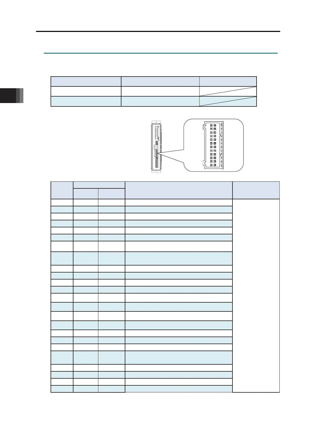
3.3.2 Connection to Actuator
Connect the cables to the motor • encoder connectors.
Motor • Encoder Connector
Model Remarks
Cable Side PADP-24V-1-S
Controller Side S24B-PADSS-1
Controller Side
Connector
Pin No.
Contents
Applicable cable
diameter
φ
φ
Cable dedicated for IAI
products
* Cable for CB and
cable for CFB are
different.
3
φ
φ
Motor drive line phase B
φ
φ
Motor drive line /Phase A
Motor drive line /Phase B
7 LS+ LDC_VCC
LS+ : Positive side of the limit switch
LDC_VCC : Loadcell Power Output
8 LS- LDC_SD+
LS- : Negative side of the limit switch
LDC_SD+ : Loadcell Communication Line Positive Side
Positive side of the brake release
Negative side of the brake release
Battery-less Absolute Communication Line Positive Side
Battery-less Absolute Communication Line Negative Side
13 A+
A+
Encoder A-phase differential + input
14 A-
A-
Encoder A-phase differential - input
15 B+
B+
Encoder B-phase differential + input
16 B-
B-
Encoder B-phase differential - input
17 CA5V CA5V CA/CB Encoder power
Encoder line driver enable output
20 LSGND LDC_SD-
LSGND : Grounding for Limit Switch
LDC_SD- : Loadcell Communication Line Negative Side
Encoder power output for CFB
1
2

 Loading...


