Precautions for Handling
Intro-12
ME0342-4B
12. PLC Timer Setting
Do not have the PLC timer setting to be done with the minimum setting.
Setting to “1” for 100ms timer turns ON at the timing from 0 to 100ms while 10ms timer from 0 to
10ms for some PLC.
Therefore, the same process as when the timer is not set is held and may cause a failure such
as the actuator cannot get positioned to the indicated position number in Positioner Mode.
Set “2” as the minimum value for the setting of 10ms timer and when setting to 100ms, use
10ms timer and set to “10”.
13. Battery-less absolute specification actuators
1) RCP5 series actuators will perform slight position adjustment operation due to
characteristics of the stepper motor during initial servo ON only, after the power is turned
ON.
Maximum travel during position adjustment operation is 0.025 x lead length [mm].
Additionally, until servo turns ON, the present position displayed on the teaching tool will be
the coordinates prior to the adjustment operation.
2) After the power is turned ON followed by the initial servo ON, home return complete signal
HEND will be output.
3) If the initial servo ON is executed outside range of the software limit, no error will be output.
After traveling within the range, monitoring of the software limit will start.
4) If the motor unit is removed from the actuator for motor replacement, etc., be sure to perform
home return motion (absolute reset).
5) There is the manufacturing number of the connectable actuator printed on the front panel of
the controller. Make sure to connect without mistake. The absolute error will occur if the
connection is wrong.
6) When using in Pulse Train Control Mode, and set Parameter No. 25 to 7.
14. Startup Time of Controller
Have 1 second or more as an initializing time at the power on (startup).
Precautions for PC connection to Controller grounded at positive terminal of 24V DC power supply
ME0342-4B Intro-13
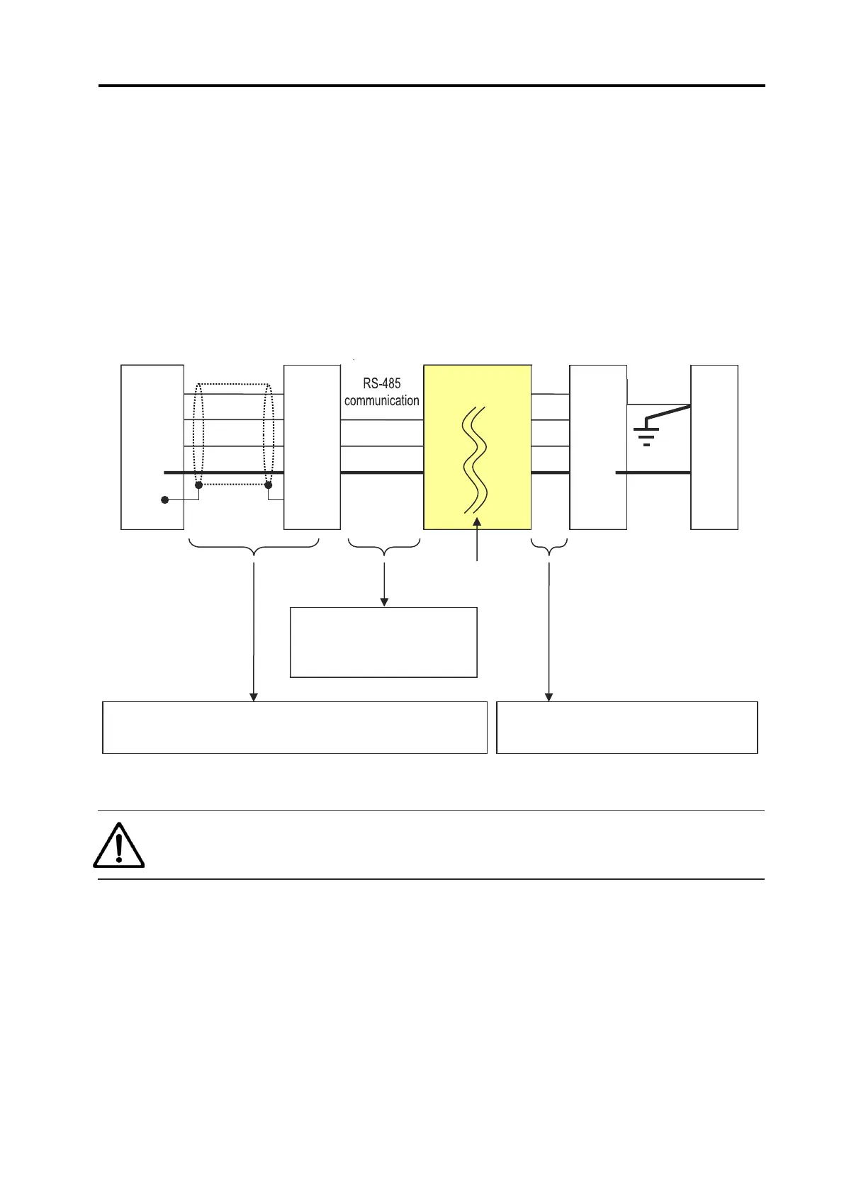
Precautions for PC connection to Controller
grounded at positive terminal of 24V DC power supply
Use the SIO isolator (RCB-ISL-SIO) in order to connect a PC on the SIO connector on the
controller when the positive side of the 24V DC power supply is grounded.
If a PC is connected to the gateway unit without using an SIO isolator, the power will short-
circuit and cause the PC to malfunction.
Caution
● RS-232 conversion unit (RCB-CV-MW) cannot be used.
GND
FG
PC
Conversion unit
(RCB-CV-USB)
5 V
SGA
SGB
GND
FG
5V1
SGA SGA1
SGB SGB1
GND GND1
FG
Gateway
unit
SIO isolator
(RCB-ISL-SIO)
Insulation
Isolator communication cable
CB-RCB-SIO***
will be required separately.
Cable included with PC software (IA-OS-C)
(USB cable (CB-SEL-USB030) & conversion unit (RCB-CV-USB))
Cable included with PC software (IA-OS-C)
(Communication cable (CB-RCA-SIO050))
5 V
SGA
SGB
GND

 Loading...


