3. Wiring
3.1 Positioner Mode (PIO Control)
3-25
ME0342-4B
8) PIO Pattern 7 ············· Force Sensor Used Pressing Mode 2 (Solenoid Valve Mode)
* in codes above shows the signal of the active low. Processing occurs when an
input signal of the type is turned OFF. An output signal of the type is normally ON
in the power-on status and turned OFF at signal output.
24V DC (NPN Type)
0V (PNP Type)
Calibration Command
Brake Control Release
Operation Mode Changeover
Home Return
Pause
Reset
Servo ON
0V (NPN Type)
24V DC (PNP Type)
●――
●――
●――
●――
●――
●――
●――
●――
●――
●――
●――
●――
1B
2B
3B
4B
5B
6B
7B
8B
9B
10B
11B
12B
13B
14B
15B
16B
17B
18B
19B
20B
PE0 ――■
PE1 ――■
PE2 ――■
PE3 ――■
PE4 ――■
TQRS ――■
LOAD ――■
CEND ――■
――■
RMDS ――■
HEND ――■
PEND ――■
SV ――■
*EMGS ――■
*ALM ――■
*ALML ――■
――■
――■
N ――■
N ――■
Loadcell Calibration Complete
―――(
―――(
―――(
―――(
―――――(
―――――(
―――――(
―――――(
―――――(
―――(
―――(
―――(
―――――(
―――――(
―――――(
―――――(
―――――(
―――(
―――――(
―――――(
3.2 Pulse Train Control Mode
ME0342-4B 3-26
3.2 Pulse Train Control Mode
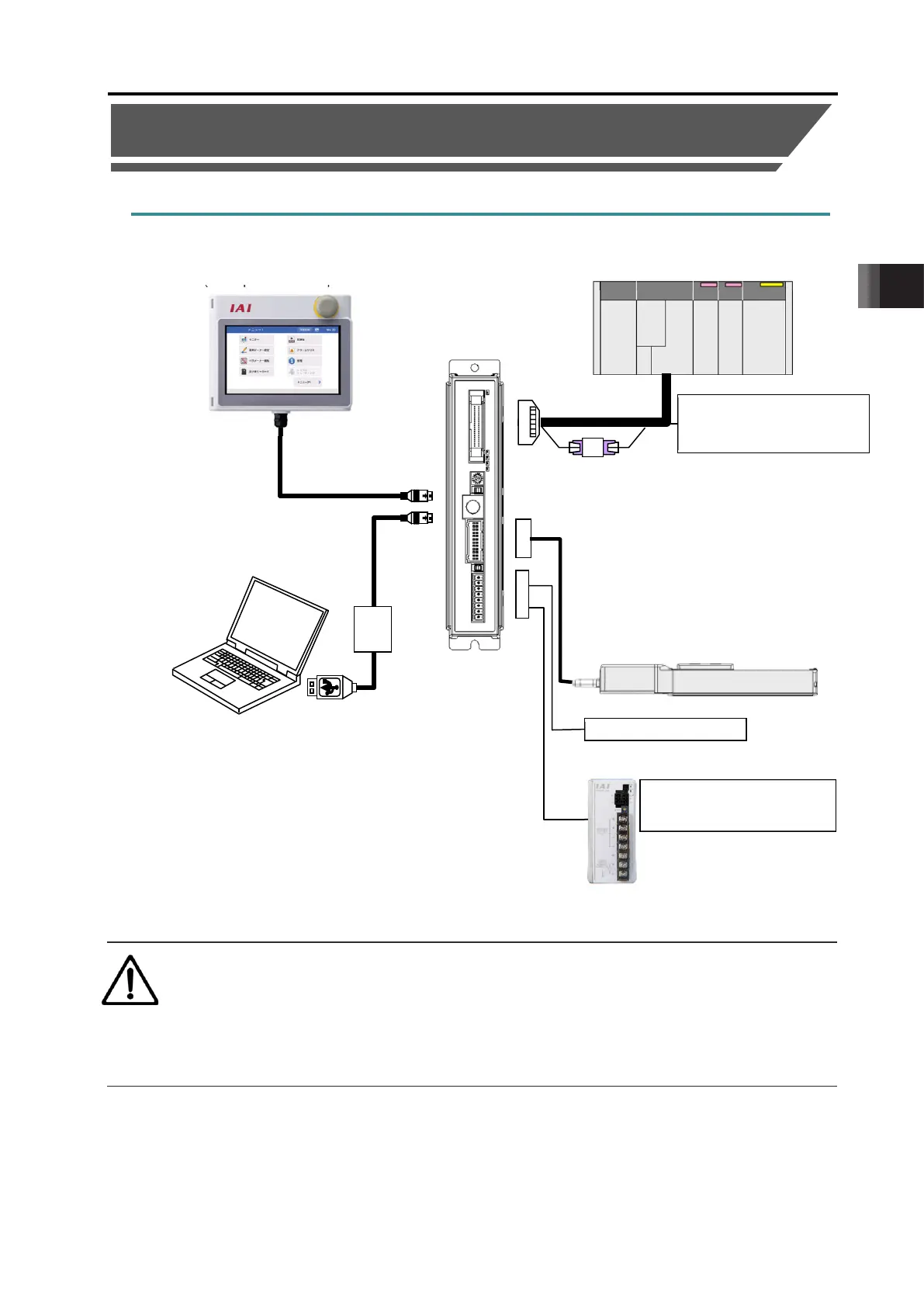
3.2.1 Wiring Diagram (Connection of Devices)
Caution
Make sure to turn the power to the controller OFF when inserting or removing the
connector that connects the PC software or teaching pendant.
Inserting or removing the connector while the power is turned ON causes a controller
failure.
Teaching Pendant
(to be purchased separately)
PC dedicated teaching software
(to be purchased separately)
Host System
(PLC, etc.…Please prepare separately)
(24V DC
…Please prepare separately)
Control/Driving Power Supply
(24V DC
…Please prepare separately)
AK-04 (to be purchased separately)
Necessary when host positioning unit
is open collector output.

 Loading...


