3. Wiring
3.1 Positioner Mode (PIO Control)
3-7 ME0342-4B
S1
S2
MPI
MPO
24V
0V
24V
0V
EMG-
BK
Power Supply
Connector
Switch on the
Teaching Pendant
Control
Power
Supply
SIO Connector
PCON
Wiring Condected
at Delivery
Motor Power Supply
Emergency Stop Control Circuit
Brake Release Power Supply
(Note) Supply 24V when connecting actuator
equipped with brake and release brake
compulsorily
Drive Cutoff
Circuit
The emergency stop
switch is activated.
please prepare
separately)
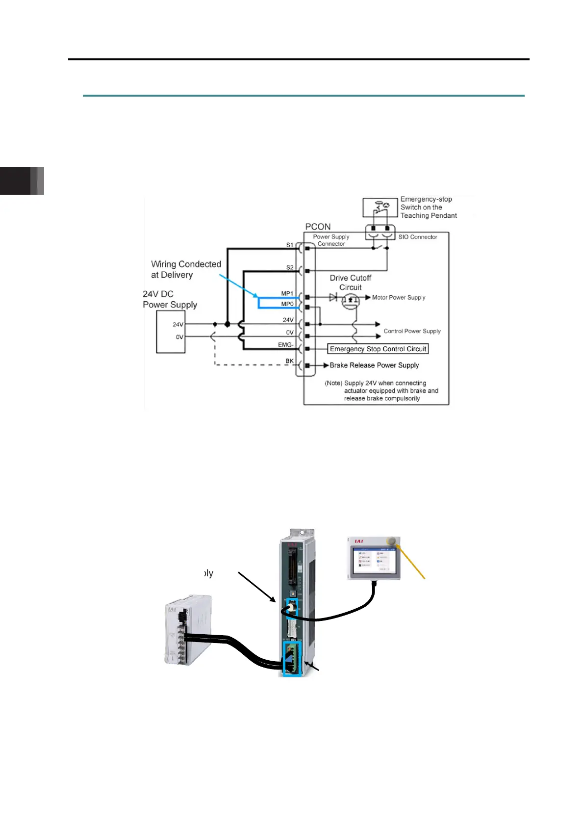
3.1.3 Wiring
[1] Power Supply Connector (for Power Supply and Emergency Stop)
As an example of a circuit, cases of 4 conditions are shown. Select from 3) or 4) for CGB type.
1) Activate the stop switch on the teaching pendant to activate an actuator
● Example of Circuit
The emergency stop input to the controller gets inactivated by supplying +24V continuously to
EMG- Terminal. +24V is connected to EMG- via the emergency stop switch on the teaching
pendant.
● Image of Wiring

 Loading...


