9. Appendix
9.1 Way to Set Multiple Controllers with 1 Teaching Tool
9-2 ME0342-4B
9.1.1 Connecting Example
Caution
Supply 0V to the SIO converter and each controller from the same power source.
Cable Included in PC software
<CB-SEL-USB030、RCB-CV-USB、CB-RCA-SIO□□□>
<RCB-CV-MW、CB-RCA-SIO□□□>
PC Software IA-OS
IA-OS(
PC Software DVD-ROM only)
IA-OS-C(Cable included)
RC/EC PC software
RCM-101-MW (RS232C-competible)
RCM-101-USB (USB-compatible)
SIO Converter (with Terminal Resistor)
<RCB-TU-SIO-A> (Vertical)
<RCB-TU-SIO-B> (Horizontal)
e-CON Connector (Manufactured by AMP 4-1473562-4: Housing Color Green)
e-CON Connector (Manufactured by AMP 3-1473562-4: Housing Color Orange)
Junction (Manufactured by AMP 5-1473574-4)
To be prepared by customer.
9.1 Way to Set Multiple Controllers with 1 Teaching Tool
ME0342-4B 9-3
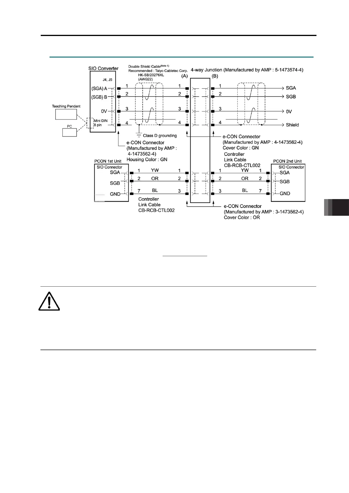
9.1.2 Detailed Connection Diagram of Communication Lines
Note 1 Apply a 2-pair shielded cable.
When connecting a cable other than recommended to (A) and (B), make sure to use a
hard-cored cable equivalent to the vinyl cable (KIV) dedicated for control devices with
the sheath outer diameter from 1.35 to 1.60mm. Using cables with outer diameter out
of the specification may cause poor contact to occur.
Caution
When cables with outer diameter out of the specification are used, use a terminal block
instead of 4-direction junction. In this configuration, disconnect the e-CON connector of
the link cable.
If an error possibly caused by poor contact occurs frequently, replace the junction with the
terminal block.

 Loading...


