3. Wiring
3.1 Positioner Mode (PIO Control)
3-1
ME0342-4B
3.1 Positioner Mode (PIO Control)
3.1.1 Wiring Diagram (Connection of Devices)
Caution
Make sure to turn the power to the controller OFF when inserting or removing the
connector that connects the PC software or teaching pendant to the controller.
Inserting or removing the connector while the power is turned ON causes a controller
failure.
Teaching Pendant
(to be purchased separately)
PC Software
(to be purchased separately)
Host System
(PLC, etc.…Please prepare separately)
Please prepare separately)
Control/Driving Power Supply
(24V DC
…Please prepare separately)
3.1 Positioner Mode (PIO Control)
ME0342-4B 3-2
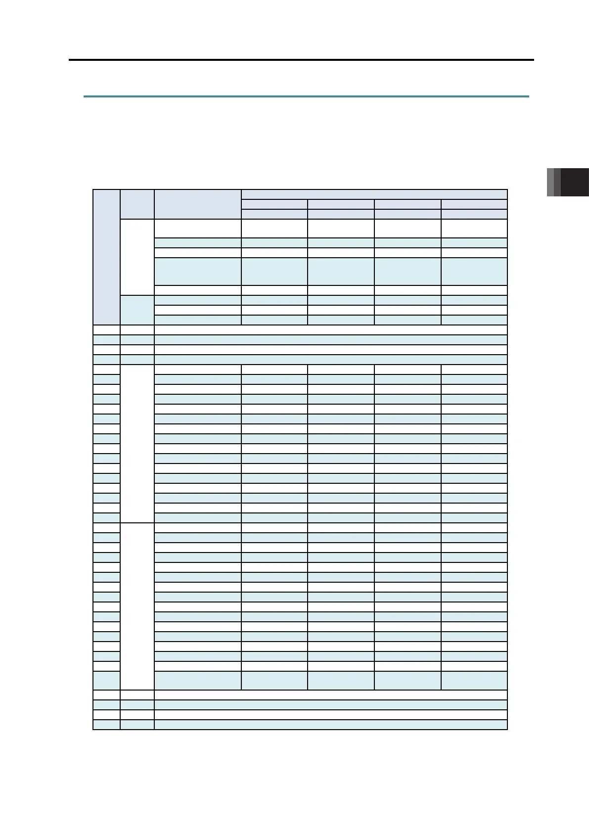
3.1.2 PIO Pattern Selection and PIO Signal
[1] PIO Patterns and Signal Assignment
The signal assignment of I/O flat cable by the PIO pattern is as shown below. Follow the
following table to connect the external equipment (such as PLC).
Pin
No.
Category
PIO Functions
Parameter No.25 “PIO Pattern” Selection
Input
Number of positioning
points
64 points 64 points 256 points 512 points
(Current position
× × ×
Output
Input
Output
16B OUT15
*ALML

 Loading...


