3. Wiring
3.3 Wiring Method
3-43
ME0342-4B
3.3.2 Connection to Actuator
Connect the cables to the motor • encoder connectors.
Motor • Encoder Connector
Model Remarks
Cable Side PADP-24V-1-S
Controller Side S24B-PADSS-1
Controller Side
Connector
Pin No.
Contents
Applicable cable
diameter
Cable dedicated for IAI
products
* Cable for CB and
cable for CFB are
different.
Motor drive line /Phase A
Motor drive line /Phase B
LS+ : Positive side of the limit switch
LDC_VCC : Loadcell Power Output
8 LS- LDC_SD+
LS- : Negative side of the limit switch
LDC_SD+ : Loadcell Communication Line Positive Side
Positive side of the brake release
Negative side of the brake release
Battery-less Absolute Communication Line Positive Side
Battery-less Absolute Communication Line Negative Side
13 A+
A+
Encoder A-phase differential + input
14 A-
A-
Encoder A-phase differential - input
15 B+
B+
Encoder B-phase differential + input
16 B-
B-
Encoder B-phase differential - input
17 CA5V CA5V CA/CB Encoder power
Encoder line driver enable output
20 LSGND LDC_SD-
LSGND : Grounding for Limit Switch
LDC_SD- : Loadcell Communication Line Negative Side
Encoder power output for CFB
3.3 Wiring Method
ME0342-4B 3-44
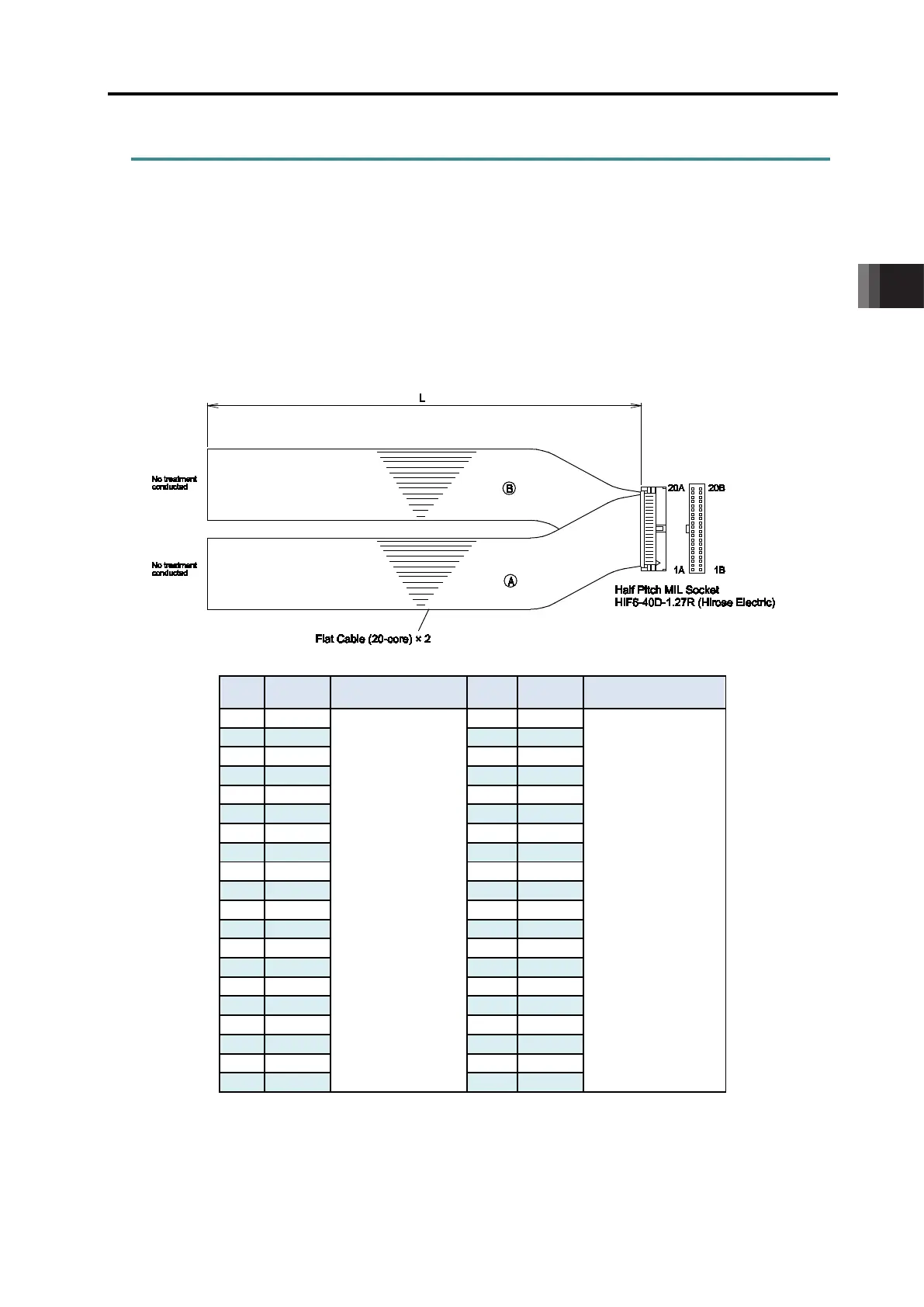
3.3.3 Connection of PIO
Conduct the connection of I/O to the controller is to be carried out using the dedicated I/O cable.
The cable length is shown in the model code of the controller. Refer to [2.1.4 How to read the
model] for details. There are 2m for standard, 3m and 5m as an option. Up to 10m I/O cables
are sold separately.
Also, the end opposite the connector of the cable harness is just cut and no treatment is
conducted so the wiring layout can be performed freely to the host controller (such as PLC).
Model : CB-PAC-PIO□□□(□□□ indicates the cable length L. Example. 020 = 2m)
No.
Wiring No.
Wiring
Flat Cable ○A
(Press Welding)
AWG28
Flat Cable ○B
(Press Welding)
AWG28
For the signal assignment of each wire, refer to the following considering the operation mode.
1) Positioner Mode ······················· [3.1.3 [4] PIO Circuit]
2) Pulse Train Control Mode··········· [3.2.3 [3] PIO Circuit]

 Loading...


