2. Specications
2.2 Operation Modes and Functions
2-10 ME0342-4B
[2] List of Applicable Field Networks
Applicable for the field network shown in the list below.
Except for RS485 (Modbus), it is the option which can be selected when purchasing. It cannot
be changed after the product is delivered.
Also, for the field network other than RS485, PIO cannot be equipped. And Pulse Train Mode
cannot be operated.
PCON-CB/CFB Type
Field Network Name Description Details
CC-Link
Control of the actuator is available
with I/O communication using the
control signals same as those for PIO
or the numerical data communication.
Refer to the other ME0254
(Note1)
CC-Link IE Field Refer to the other ME0389
(Note1)
CompoNet Refer to the other ME0220
(Note1)
DeviceNet Refer to the other ME0256
(Note1)
EtherCAT Refer to the other ME0273
(Note1)
EtherNet/IP Refer to the other ME0278
(Note1)
MECHATROLINK-I/II Refer to the other ME0221
(Note1)
PROFIBUS-DP Refer to the other ME0258
(Note1)
PROFINET IO Refer to the other ME0333
(Note1)
MECHATROLINK-III
Synchronized control of several
actuators in highly constant periodicity
is available.
Refer to the other ME0317
(Note1)
RS485
Actuator is controlled with using a
general protocol “Modbus”
Refer to the other ME0162
(Note1)
Caution
(Note 1) PCON-CB/CFB/CBP are the slave units (slave stations). Refer to the instruction
manual of the master unit of each supplier and PLC to be mounted for the details
of each network.
For the instruction of the field network for PCON-CB/CFB, the instruction manual
is provided separately. Use the manual together with this manual.
2.3 List of Basic Specifications
ME0342-4B 2-11
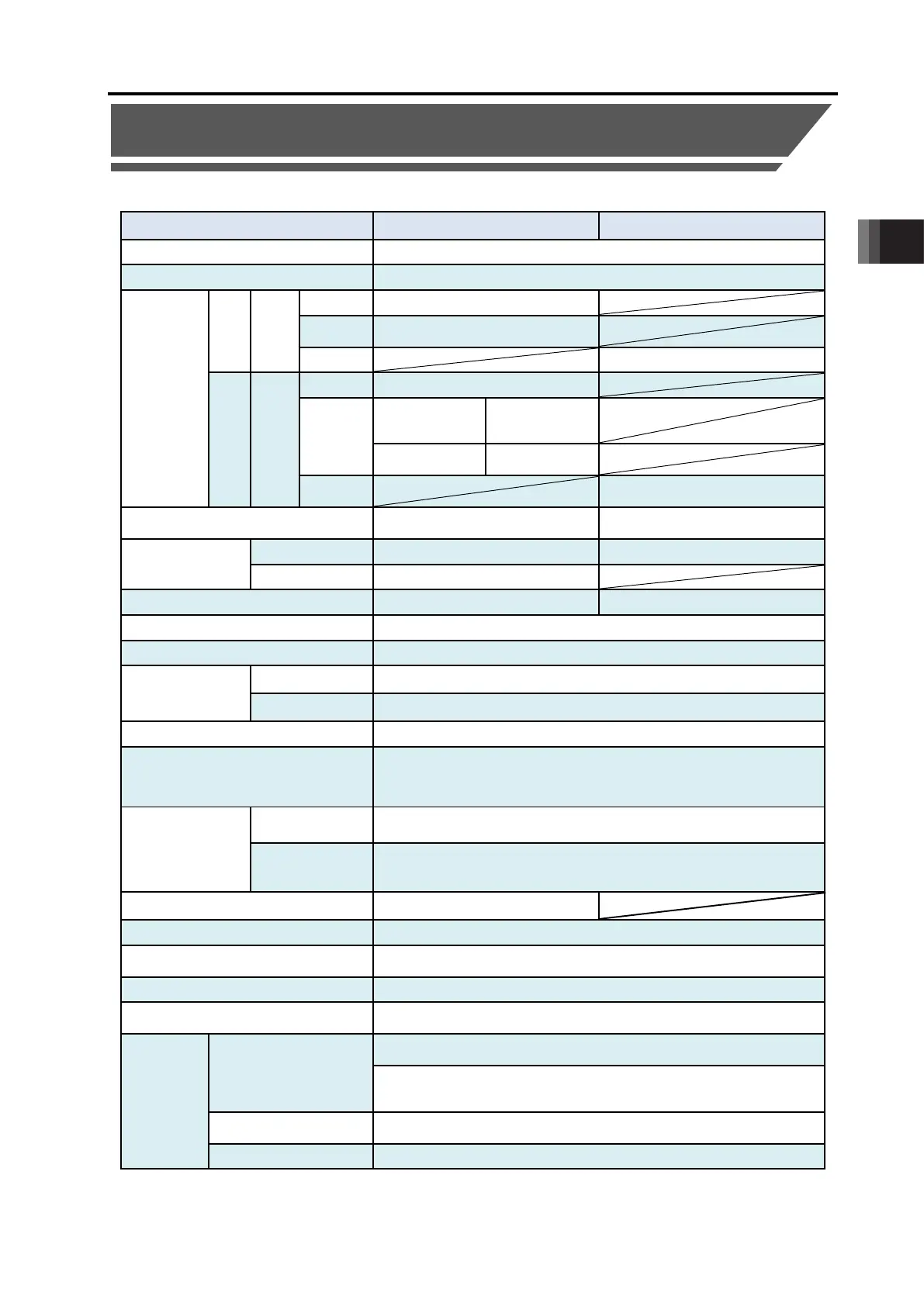
2.3 List of Basic Specifications
The specifications of this product are as shown below.
Item PCON-CB/CGB/CBP/CGBP PCON-CFB/CGFB
Number of controlled axes 1-axis
Power-supply Voltage
24V DC ±10%
Load current
(including
control side
current
consumption)
(Note 1)
RCP2
RCP3
Motor
Type
20P, 28P MAX. 1.0A
MAX. 2.2A
60P, 86P MAX. 6A
RCP4
RCP5
RCP6
Motor
Type
28P MAX. 1.0A
35P, 42P,
42SP, 56P
function is
MAX. 2.2A
High-thrust
function is enabled
MAX. 6A
Power Supply for Electromagnetic Brake
(for actuator equipped with brake)
24V DC ±10% 0.15A (MAX.) 24V DC ±10% 0.5A (MAX.)
Heat Generation
RCP2, RCP3 5W 19.2W
RCP4 to RCP6 8W
Rush Current
(Note 2)
8.3A 10A
Transient Power Cutoff Durability
MAX.500µs
Motor Control System Weak field-magnet vector control
Corresponding
Encoder
RCP2 to RCP5 Incremental encoder, Battery-less absolute encoder Resolution 800pulse/rev
RCP6 Battery-less absolute encoder Resolution 8192pulse/rev
Motor/Encoder Cable Length MAX. 20m
Serial Communication Interface
(SIO Port)
RS485 : 1 channel (based on Modbus Protocol RTU/ASCII)
Speed : 9.6 to 230.4Kbps
Control available with serial communication in the modes other than the pulse
External Interface
PIO Type
Signal I/O dedicated for 24V DC (selected from NPN/PNP)
…
Input 16 points
max., output 16 points max. Cable length MAX. 10m
Field Network Type
DeviceNet, CC-Link, CC-Link IE Field, PROFIBUS-DP, CompoNet,
MECHATROLINK-I/II, EtherCAT, EtherNet/IP, PROFINET IO,
(Note 3)
Loadcell Interface
(Note 4)
Communication method : RS485
Data Setting and Input PC Software, Touch Panel Teaching Pendant
Data Retention Memory
Saves position data and parameters to non-volatile memory
(There is no limitation in number of writing.)
Operation Mode Positioner Mode/Pulse Train Control Mode (selected by parameter setting)
Number of Positions in Positioner Mode
Standard 64 points, MAX. 512 points
(Note) Number of positions differs depending on the selection in PIO pattern.
Pulse Train
Interface
(Note 5)
Input Pulse
Differential System (Line Driver System) : MAX. 200kpps
Cable length MAX. 10m
Open Collector System : Not applicable.
* If the host applies the open collector output, prepare AK-04 (option)
separately to convert to the differential type.
Command Pulse Multiplying
Factor (Electrical Gear : A/B)
1/50 < A/B < 50/1
Setting Range of A and B (set to parameter) : 1 to 4096
Feedback Pulse Output None

 Loading...


