4. Operation
4.2 Operation in Positioner Mode
4-10
ME0342-4B
[2] Overview of Major Functions
Major functions Description
Number of positioning points Number of positioning points which can be set in the position table.
Operation with the Position No.
Input
Normal operation started by turning the start signal ON after position
No. is entered with binary data.
Position No. direct command
operation
Operation by turning on the signal directly corresponding to a
position number
Positioning
Positioning at an arbitrary position by the data set in the position
table
Velocity change during the
movement
Velocity change by activating another position number during
movement
Pressing (tension)
Operation by an arbitrary pressing (tensile) force set in the position
table
Force Sensor Used Pressing
(* PCON-CBP/CGBP only)
Pressing operation with high precision to be performed by
measuring the current pressing force on the force sensor (loadcell)
Pitch Feeding
(relative moving feed)
Pitch feed by an arbitrary moving distance set in the position table
Home return signal input
Input signal exclusively used for home return. Set to ON to start
home return
Pause
The operation can be interrupted or continued by setting this signal
to ON or OFF, respectively.
Jog moving signal The actuator moves while the input is set to on only
Teaching signal input (Current
Position Writing)
Setting the input signal to ON allows the coordinate value in the stop
state to be written to the position table.
Brake release signal input The brake (option) is to be released while the input is set to on only
Moving signal output The output signal is set to ON while the actuator is moved.
Zone signal output
The output signal is set to ON while the actuator is entered within
the zone defined by the coordinate values set as parameters.
Position zone signal output
The output signal is set to ON while the actuator is entered within
the zone defined by the coordinate values set in the position table.
Position Detection Feedback
Pulse Output
A feedback pulse from an encoder is to be output differentially. Refer
to [4.3 Operation in Pulse Train Control Mode] for details.
4.2 Operation in Positioner Mode
ME0342-4B 4-11
4.2.1 Operation Modes of Rotary Actuator in Multiple Rotation Mode and
Command Limitations
An actuator of multi-rotation specification includes two operation modes, the normal mode
enabling only a limited number of rotations and the index mode
(Note 1)
enabling a number of
rotations.
A specific operation mode can be selected by parameter No.79 “Rotary axis mode selection”.
Parameter No.80 “Rotary axis shortcut selection” allows the shortcut to be made valid or
invalid.
Note 1 There are limitations in operation in Index Mode for Rotary Actuator.
Refer to [Caution in Handling in the preliminaries]
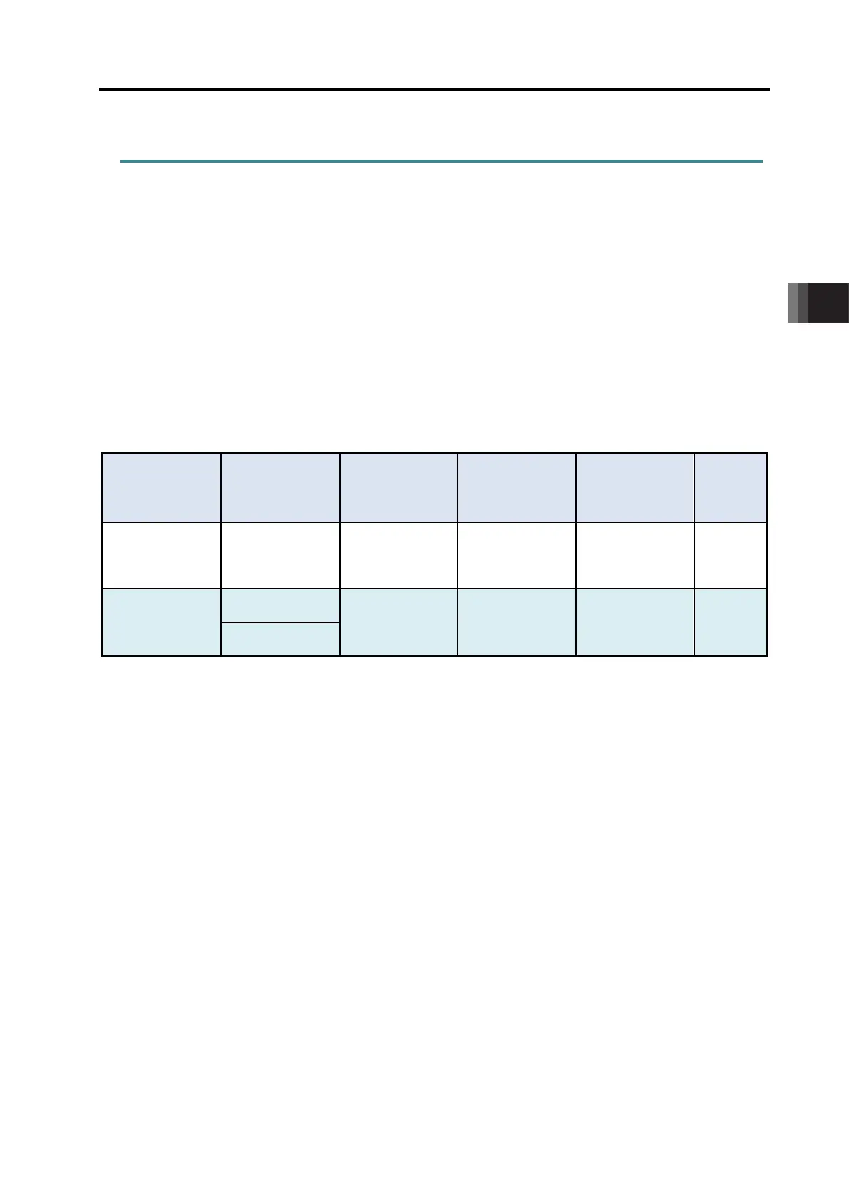
The table below lists the settings of parameters and the operation specification in each mode.
Rotary axis
mode selection
Parameter No.79
Rotary axis
shortcut selection
Parameter No.80
Current position
indication
Absolute
position
command zone
Relative
position
command zone
Soft
Limit
Enabling/
0
(Normal Mode)
0 (Disabled)
-9999.99
to 9999.99
(Note 2)
-0.15
to 9999.15
(Note 2)
-9999.30
to 9999.30
(Note 2)
Enabled
1
(Index Mode)
0 (Disabled)
0 to 359.99 0 to 359.99
-360.00
to 360.00
Disabled
1 (Enabled)
Note 2 It is limited within the range of the software limit.

 Loading...


