4. Operation
4.1 Basic Operation
4-8
ME0342-4B
4.1.3 Parameter Settings
Parameter data should be set to be suited to the system or application. Parameters are
variables to be set to meet the use of the controller in the similar way as settings of the ringtone
and silent mode of a cell phone and settings of clocks and calendars.
(Example for Parameter Setting)
Soft Stroke Limit : Set a proper operation range for definition of the stroke end, prevention
of interferences with peripherals and safety.
Zone Output : Set to require signal outputs in an arbitrary position zone within the
operation zone.
Parameters should be set to meet the use of the controller prior to operation. Once set, they
may not set every operation.
Refer to [Chapter 6 Parameter] for the parameter types and the details.
4.2 Operation in Positioner Mode
ME0342-4B 4-9
4.2 Operation in Positioner Mode
There are 6 types from PIO Pattern 0 to 5 of control systems equipped in PCON-CB and 8 types
from PIO Pattern 0 to 7 in PCON-C B P.
In case of conducting a control, set a PIO pattern suitable for your purpose to Parameter No. 25
"PIO Pattern Select".
The PIO Pattern cannot be switched over after the system is finished to be established or during
the actuator operation. Choose the optimum pattern beforehand considering the system
operation specifications and prepare the cables and sequence design.
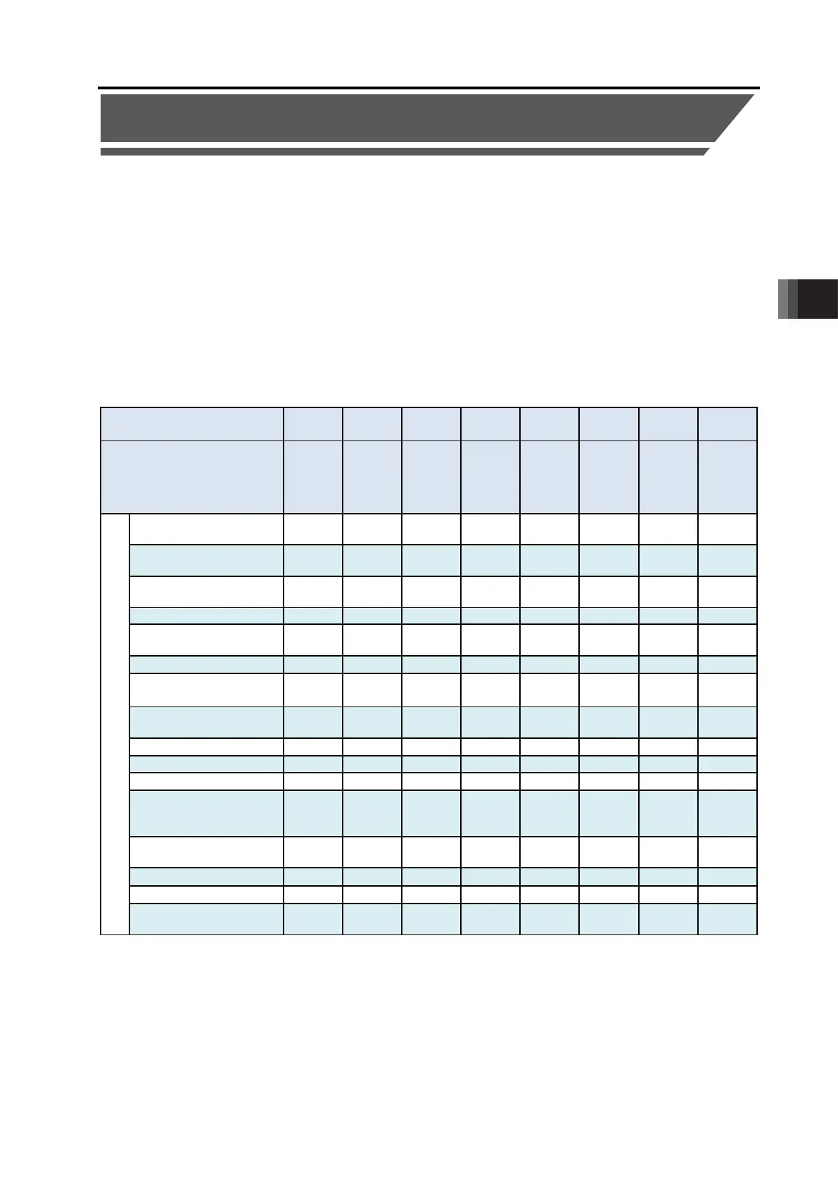
[1] PIO Pattern Selection and Main Functions
: Shows Effective Feature
PIO Pattern
(Parameter No.25)
0 1 2 3 4 5 6 7
Mode
mode
mode
256-
mode
-
mode
valve
mode 1
valve
mode 2
Sensor
Used
Sensor
Used
Major functions
Number of positioning
points
64 64 256 512 7 3 32 5
Operation with the
Position No. Input
× ×
×
Position No. direct
command operation
× × × ×
×
Velocity change during
the movement
× ×
×
Force Sensor Used
Pressing
× × × × × ×
Pitch Feeding
(relative moving feed)
×
(Current Position
×
× × × × × ×
Brake release signal
input
×
Position zone signal
output
×
*1 The pause signal is not provided. Refer to [4.2.7 [5]]
(Reference)
Zone signal output signal : The zone range is set to the Parameters No.1 and 2 and becomes
always effective after the home return is complete.
Position zone signal : This feature is associated with the specified position number. The zone
range is set in the position table. The zone range is enabled only when
the position is specified but disabled if another position is specified.

 Loading...


