4. Operation
4.3 Pulse Train Control Mode
4-120 ME0342-4B
4.3.4 Settings of Basic Parameters Required for Operation
It is a mandatory parameter to perform an operation.
(The parameters listed in the table below may only be set if the actuator performs only
positioning operation.)
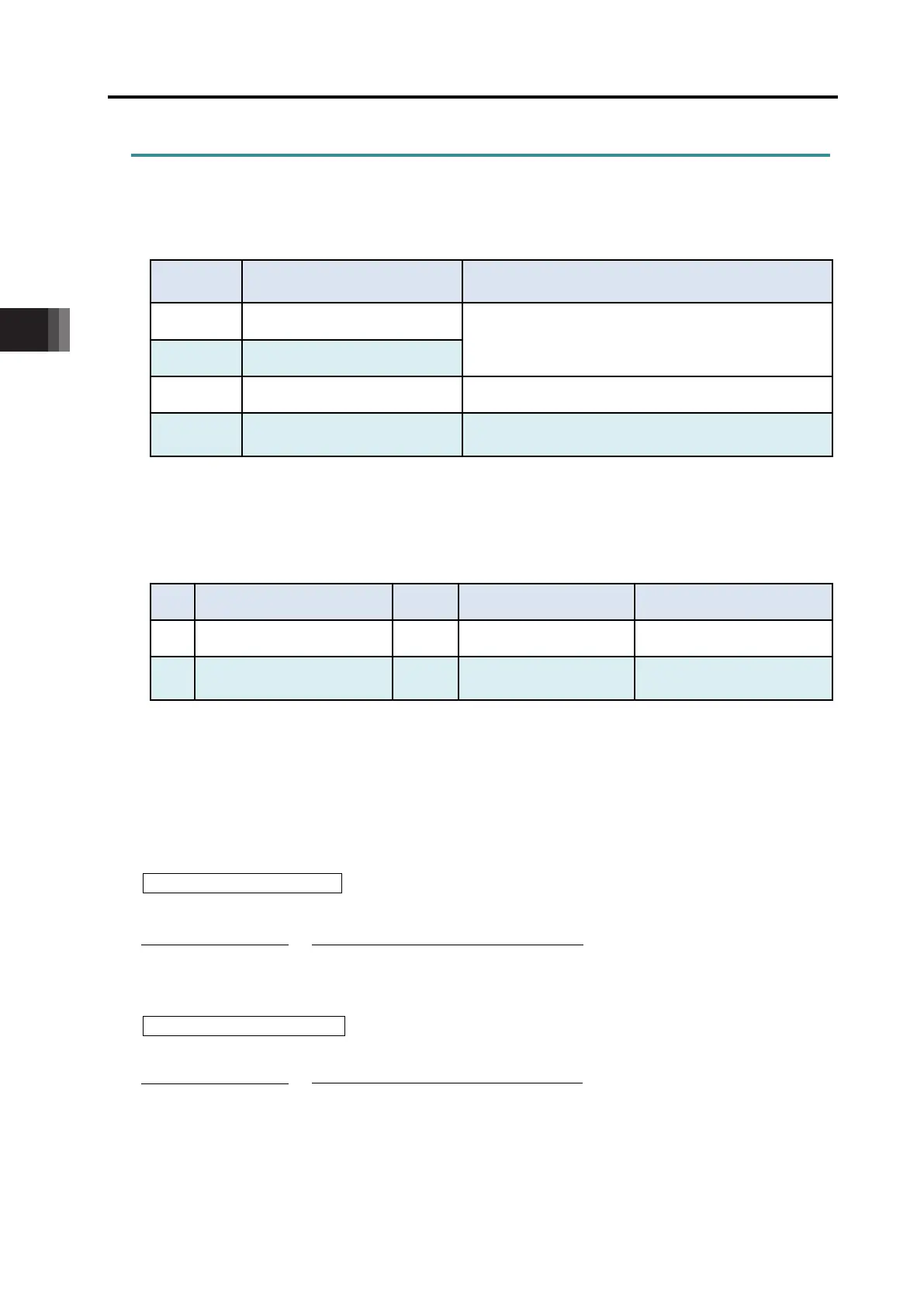
Name Details
65 Electronic Gear Numerator
This parameter determines the unit travel distance of
the actuator per command pulse train input 1 pulse.
66 Electronic Gear Denominator
63 Command Pulse Mode
Specifies the command pulse train input mode.
64
Command Pulse Mode Input
Polarity
Sets the type of active high/low of the specified pulse
train
[1] Electronic Gear Setting
This parameter settings the unit travel distance of the actuator per command pulse train input 1 pulse.
User Parameter No.65/No.66 Electronic Gear Numerator/Denominator
No. Name Unit Input Range Default factory setting
65 Electronic Gear Numerator
– 1 to 4096 200
66
Electronic Gear
Denominator
– 1 to 4096 200
Determine the movement amount and calculate value for the electronic gear setting by following
the formula below:
Linear Axis Unit Travel Distance: Min. Travel Distance Unit (1, 0.1, 0.01mm etc.) /pulse
Rotary Axis Unit Travel Distance: Min. Travel Distance Unit (1, 0.1, 0.01deg. etc.) /pulse
Electronic Gear Formula:
In the case of Linear Axis
In the case of Rotary Axis
Note 1 Refer to [9.4 List of Specifications of Connectable Actuators] for the encoder pulse of
each actuator.
Electronic Gear
Numerator
Electronic Gear
Numerator
Denominator
No. of Encoder Pulses
(Note 1)
[pulse/rev]
Actuator Lead Length [mm/rev]
Unit Travel Distance [mm/pulse]
No. of Encoder Pules [pulse/rev]
360 [deg/rev]
×
Rotary Axis Reduction Ratio
Unit Travel Distance [deg/pulse]
Electronic Gear
Denominator

 Loading...


