4. Operation
4.3 Pulse Train Control Mode
4-120
ME0342-4B
4.3.4 Settings of Basic Parameters Required for Operation
It is a mandatory parameter to perform an operation.
(The parameters listed in the table below may only be set if the actuator performs only
positioning operation.)
Name Details
65 Electronic Gear Numerator
This parameter determines the unit travel distance of
the actuator per command pulse train input 1 pulse.
66 Electronic Gear Denominator
63 Command Pulse Mode
Specifies the command pulse train input mode.
64
Command Pulse Mode Input
Polarity
Sets the type of active high/low of the specified pulse
train
[1] Electronic Gear Setting
This parameter settings the unit travel distance of the actuator per command pulse train input 1 pulse.
User Parameter No.65/No.66 Electronic Gear Numerator/Denominator
No. Name Unit Input Range Default factory setting
65 Electronic Gear Numerator
– 1 to 4096 200
66
Electronic Gear
Denominator
– 1 to 4096 200
Determine the movement amount and calculate value for the electronic gear setting by following
the formula below:
Linear Axis Unit Travel Distance: Min. Travel Distance Unit (1, 0.1, 0.01mm etc.) /pulse
Rotary Axis Unit Travel Distance: Min. Travel Distance Unit (1, 0.1, 0.01deg. etc.) /pulse
Electronic Gear Formula:
In the case of Linear Axis
In the case of Rotary Axis
Note 1 Refer to [9.4 List of Specifications of Connectable Actuators] for the encoder pulse of
each actuator.
Electronic Gear
Numerator
Electronic Gear
Numerator
No. of Encoder Pulses
(Note 1)
[pulse/rev]
Actuator Lead Length [mm/rev]
Unit Travel Distance [mm/pulse]
No. of Encoder Pules [pulse/rev]
360 [deg/rev]
×
Rotary Axis Reduction Ratio
Unit Travel Distance [deg/pulse]
Electronic Gear
Denominator
4.3 Pulse Train Control Mode
ME0342-4B 4-121
Formula for velocity:
The velocity of the actuator can be figured out with the following formula.
Velocity = Unit Travel Distance × Input Pulse Frequency [Hz]
Examples of electronic gear calculations:
To set the unit travel distance to 0.01 (1/100) mm for an actuator a ball screw lead of 3mm,
equipped with an encoder of 800pulses/rev.
The electronic gear numerator is calculated as 8, while the electronic gear denominator is
calculated as 3. Based on these settings, the travel distance per command pulse train input
pulse becomes 0.01mm.
Caution
● The fraction has to be completely reduced so both the electric gear numerator and
electric gear denominator can be 4096 or less and make them to be integral numbers.
(Do not stop reducing the fraction on the way.)
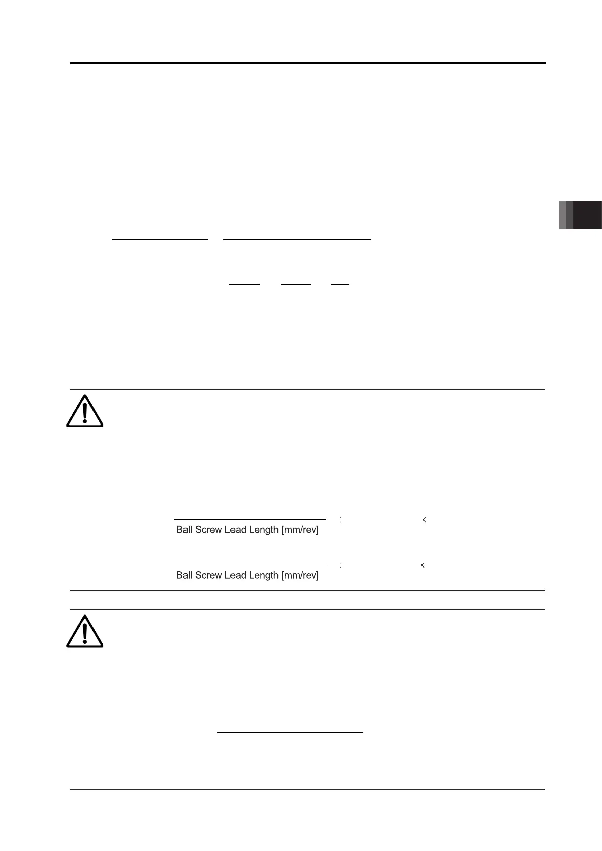
● Electronic gear numerator and electronic gear denominator on the line axis have to
satisfy the following relative formulas.
Caution
● Use rotary actuators of multi-rotation specification within the range where the following
formula is satisfied. Moreover, the maximum rotation angle is ±9999 [deg] (maximum
software stroke limit).
● Electronic gear numerator and electronic gear denominator on the line axis have to
satisfy the following relative formulas.
Maximum rotation angle : Set the usage conditions (MAX.-9999 to 9999 [deg])
Unit Travel Distance : Travel distance per command pulse
No. of Encoder
Pluses [pulse]
Numerator
Maximum rotation angle [deg]
31
Unit Travel Distance [deg/pulse]
Pluses [pulse]
Denominator
No. of Encoder Pluses [pulse/rev]
Ball Screw Lead Length [mm/rev]
Unit Travel Distance [mm/pulse]
Electronic Gear
Numerator
Electronic Gear
Denominator

 Loading...


