6. Parameter
6.1 Parameter
6-57
ME0342-4B
[How to Figure out Setting Value]
For the lead and the encoder pulse count of each actuator, refer to [9.4.1 Specifications of
Actuators].
For Linear Axis
Lead Length × Numerator of Electronic Gear (Parameter No.65) × 2,000
Encoder Pulse Count × Denominator of Electronic Gear (Parameter No.65) × Min. Use Velocity
(Note2)
For Rotary Axis
360 × Gear Ratio of Rotary Axis × Numerator of Electronic Gear (Parameter No.65) × 2,000
Encoder Pulse Count × Denominator of Electronic Gear (Parameter No.65) × Min. Use Velocity
(Note2)
Set the rounded up value when the calculation result is greater than 1.
There is no need of change from the default when the calculation result is 1 or smaller.
Note 1 It is necessary to make a change when a low velocity operation with the movement
amount for 1ms below 2 pulses.
Note 2 Minimum use velocity ... The most slow velocity available for operation
[104] Network Number (Parameter No.188)
No. Name Unit Input range
Default initial value setting
188 Network Number - 1 to 239 1
This parameter is exclusively used for the Field Network (CC-Link IE Field).
Refer to separate volume, [CC-Link IE Field Instruction Manual (ME0389)]
[105] Select Load Monitoring Symbol (Parameter No.198) …Pulse press only
No. Name Unit Input range
Default initial value setting
198
Select Load Monitoring
Symbol
0: Compression Load
1: Tension Load
0
It is a parameter that enables to select the symbol of the monitoring values in accordance with
the condition to use. Set it to "0" and the direction to compress should be set as the positive
value, and set it to "1" and the direction to apply tension should be set as the positive value for
monitoring.
T =
T =
6.2 Servo Adjustment
ME0342-4B 6-58
6.2 Servo Adjustment
At shipment from factory, parameters are set so that operation at rated load (maximum) is within
the payload capacity of the actuator and with stable operating characteristics.
However, at the actual usage sites, it may be necessary to perform servo adjustment.
This section explains the basic servo adjustment method.
Caution
● It is dangerous to make excessive settings suddenly. Damage to the equipment or the
actuator or injury may occur, so proceed with caution.
● Also, make sure to keep a record as you work so that it can be restored at any time.
● If you face problems which cannot be resolved, contact IAI.
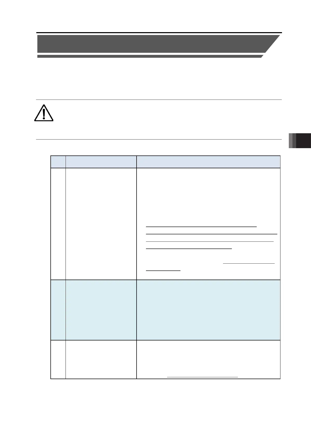
Adjustment method
No. Problems Adjustment method
1 • Positioning takes time
• Positioning accuracy is
insufficient
• Tact time needs to be
shorter
• Set Parameter No. 55 "Position Command Primary Filter
Time Constant" to "0" if it is set.
• Increase Parameter No. 7 "Servo Gain Number". The
increased set value improves tracking of position
command. As a guideline for setting, set 3 to 10, at most
15 or less. If it is too high, overshoot may occur, which
will cause sound and vibration.
• When increasing Parameter No. 7 "Servo Gain
Number", Parameter No. 31 "Velocity Loop Proportional
Gain" should also be increased accordingly in order to
ensure stability of the control system.
• When increasing Parameter No. 31 "Velocity Loop
Proportional Gain", make sure to set it to about 20% of
the initial value. Adjust Parameter No. 7 "Servo Gain
2 Vibration occurs during
acceleration/deceleration
• This may be caused by excessive
"Acceleration/Deceleration Setting," or inadequate
rigidity of the device on which the actuator is mounted.
• Lower "Acceleration/Deceleration Setting".
• Lower Parameter No. 7 "Servo Gain Number".
However, if Parameter No. 7 "Servo Gain Number" is too
low, convergence will take longer.
• Consider reinforcing the device.
• Speed irregularity occurs
during travel
• Speed accuracy is
insufficient
• Increase Parameter No. 31 "Velocity Loop Proportional
Gain". The increased set value improves tracking of
speed command. If it is too large, mechanical system
vibration may occur. As a setting guideline, try to
increase the initial values by about 20% respectively.

 Loading...


