6. Parameter
6.1 Parameter
6-57 ME0342-4B
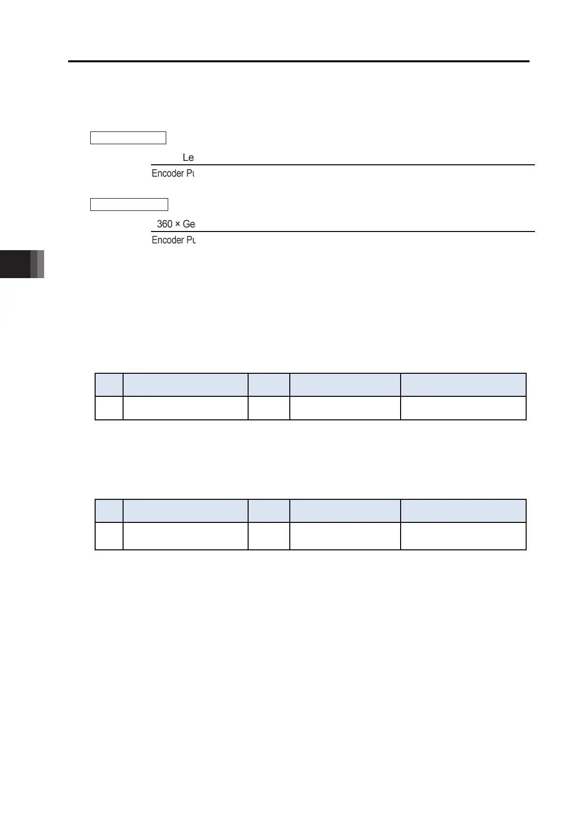
[How to Figure out Setting Value]
For the lead and the encoder pulse count of each actuator, refer to [9.4.1 Specifications of
Actuators].
For Linear Axis
Lead Length × Numerator of Electronic Gear (Parameter No.65) × 2,000
Encoder Pulse Count × Denominator of Electronic Gear (Parameter No.65) × Min. Use Velocity
(Note2)
For Rotary Axis
360 × Gear Ratio of Rotary Axis × Numerator of Electronic Gear (Parameter No.65) × 2,000
Encoder Pulse Count × Denominator of Electronic Gear (Parameter No.65) × Min. Use Velocity
(Note2)
Set the rounded up value when the calculation result is greater than 1.
There is no need of change from the default when the calculation result is 1 or smaller.
Note 1 It is necessary to make a change when a low velocity operation with the movement
amount for 1ms below 2 pulses.
Note 2 Minimum use velocity ... The most slow velocity available for operation
[104] Network Number (Parameter No.188)
No. Name Unit Input range
Default initial value setting
188 Network Number - 1 to 239 1
This parameter is exclusively used for the Field Network (CC-Link IE Field).
Refer to separate volume, [CC-Link IE Field Instruction Manual (ME0389)]
[105] Select Load Monitoring Symbol (Parameter No.198) …Pulse press only
No. Name Unit Input range
Default initial value setting
198
Select Load Monitoring
Symbol
-
0: Compression Load
1: Tension Load
0
It is a parameter that enables to select the symbol of the monitoring values in accordance with
the condition to use. Set it to "0" and the direction to compress should be set as the positive
value, and set it to "1" and the direction to apply tension should be set as the positive value for
monitoring.
T =
T =

 Loading...


