6. Parameter
6.1 Parameter
6-55
ME0342-4B
[101] Force Control Transition Threshold (Parameter No. 173) …Pulse press only
No. Name Unit Input range
Default initial value setting
173
Force control transition
threshold
% 10 to 90 In accordance with actuator
It is a parameter dedicated for the force sensor used pressing. The threshold setting for
transition from a normal movement to a force control movement considering the loadcell load
data should be established.
The setting should be established in the ratio [%] of the pressing force with the pressing current
limit as 100%.
Adjustment should be done in pitch from 5 to 10 and increase and decrease gradually.
Actuator (Pulse Press)
Standard Force
Judgment Margin [N]
Note The maximum pressing current limit value of an actuator (pulse pressing) equipped with
loadcell should differ depending on the models. Refer to [4.2.5 [4]] or [4.2.6 [3] Control
method 2)] for the maximum pressing current limit value for each model.
[102] Auto Current Adj. Select (Parameter No. 182)
No. Name Unit Input range
Default initial value setting
182 Auto current adj. select -
0: Disabled
1: Enabled
0
When automatic current down function is not used, regardless of the size of the external force,
the current set in parameter No. 12 "Current Limit During Positioning Stop" applies after
positioning stop.
When automatic current down function is enabled, it maintains the present position at the
current in accordance with the size of the external force. Effective for reduction of power
consumption when transported load is small.
For details, refer to [5.2.2 Auto current adj].
6.1 Parameter
ME0342-4B 6-56
[103]
Command Output Complete Judgement Time in Non-Positioner Mode (Parameter No.187)
…Pulse train only
No. Name Unit Input range
Default initial value setting
187
Complete Judgement
Time in Non-Positioner
ms 0 to 255 0
The setting should be established when low velocity operation
(Note 1)
is to be conducted in Pulse
Train Control Mode.
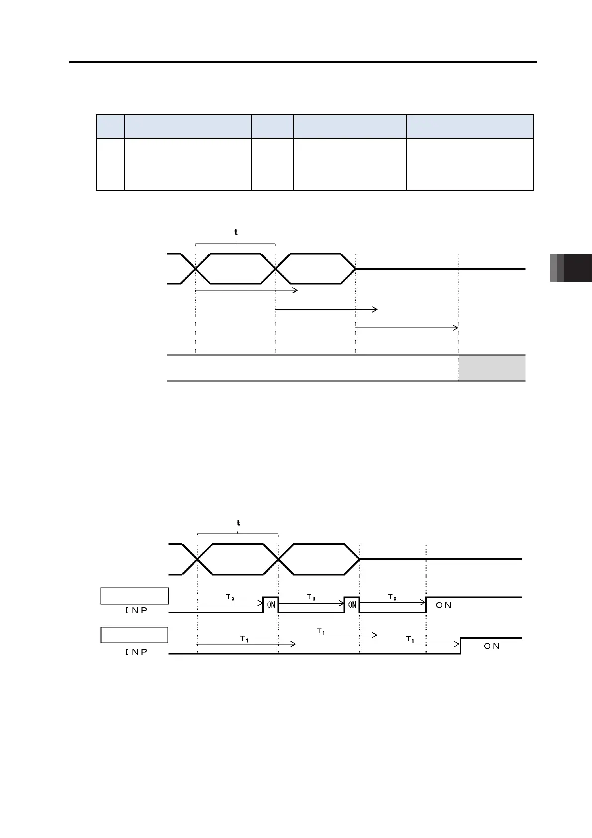
The actuator should wait for the next position command for the period of time set in this
parameter (T in the figure above) after a position command input from the host controller (PLC).
When there is no command issued from the host controller in the period of time T and also the
deviation is in the positioning band, it should be judged as a positioning complete and output the
complete signal (INP).
Therefore, if T is shorter than the pitch of duration that the position command is sent (t in the
figure above), it should be defined as a positioning complete even during operation, thus
outputs the complete signal (ONP) (Figure (1)). At that time, the torque retaining operation at the
positioning stop (refer to [6.1.2 [9] Current Limit During Positioning Stop (Parameter No. 12)])
will also be conducted, which will make the operation not smooth.
In case of (1), it is necessary to set the parameter setting T
0
longer than t.
Follow the formula in the next page to figure out the setting value.
Parameter No. 187
Setting T
Parameter No. 187
Setting T
Parameter No. 187
Setting T
Position Command
Complete
Waiting for Position Command Update (During Operation)

 Loading...


