3. Wiring
3.2 Pulse Train Control Mode
3-41
ME0342-4B
[4] Circuits for Pulse Train Control
● When Host Unit is Differential System
Caution
Make short-circuit between the host (positioning unit) and the 0V on PIO Connector.
● When Host Unit is Open Collector System
AK-04 (to be purchased separately) is required for pulse train input.
Caution
● Use the same power source for the host open collector input and output, AK-04.
● Have the cables as short as possible between the host unit and AK-04.
3.3 Wiring Method
ME0342-4B 3-42
3.3 Wiring Method
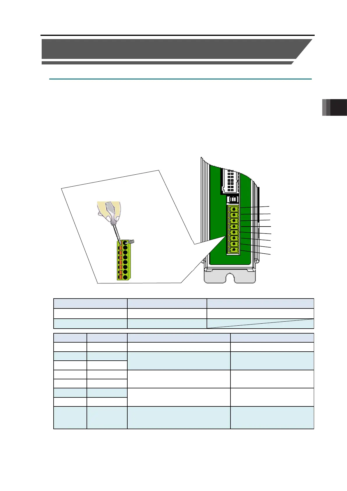
3.3.1 Wiring Layout of Power Supply Connector
The wires of the power supply and the emergency stop circuit are to be connected to the
controller enclosed connector (plug).
Strip the sheath of the applicable wires for 10mm and insert them to the connector.
1) Push a protrusion beside the inlet with a small slotted screwdriver to open the inlet.
2) After inserting a cable, remove the slotted screwdriver from the protrusion to fix the cable.
3) After establishing the wiring layout, plug in the enclosed connector to the power connector on
the controller side.
Enclosed in standard package
Applicable cable diameter
Input of emergency stop status signal
Power supply input
(24V DC ±10%)
(Note1)
KIV1.25mm
2
(AWG16)
Motor drive power line
KIV1.25mm
2
(AWG16)
Teaching pendant
Signal of emergency stop switch
KIV0.5mm
2
(AWG20)
8 BK
Brake release power supply input
(Note2)
KIV0.5mm
2
(AWG20)
Note1 If supplying power with using a 24V DC, having it turned ON/OFF, keep the 0V connected
and have the +24V supplied/cut (cut one side only).
Note2 The brake is forcibly released when +24V is supplied. Make the 0V in common with the 0V
of the power input.
connector to the
power connector on
the controller side.
screwdriver to the
-

 Loading...


