2. Specications
2.2 Operation Modes and Functions
2-6 ME0342-4B
2.2.2 Positioner Mode (PCON-CB/CBP I/O Type: NP and PN)
Refer to [3.1.3 Wiring] for wiring for each PIO pattern and [4.2 Operation in Positioner Mode] for
details of how to operate and the main features.
[1] PIO Patterns in Positioner Mode
Type
Mode Overview
PIO
Pattern 0
0
(at the
delivery)
Positioning Mode
(Standard Type)
• Number of positioning points : 64 points
• Position command : binary code
• Zone signal output : 1 point
(Note 2)
• Position zone signal output : 1 point
PIO
Pattern 1
1
Teaching Mode
(Teaching type)
• Number of positioning points : 64 points
• Position command : binary code
• Position zone signal output : 1 point
(Note 2)
• Jog operation enabled by PIO signal
• Writing current position data to position table
• Number of positioning points : 256 points
• Position command : binary code
• Position zone signal output : 1 point
• Number of positioning points : 512 points
• Position command : binary code
• Zone signal output : None
PIO
Pattern 4
4
Solenoid Valve Mode 1
(7-point type)
• Number of positioning points : 7 points
• Position command : Individual number signal ON
• Zone signal output : 1 point
(Note 2)
• Position zone signal output : 1 point
PIO
Pattern 5
5
Solenoid Valve Mode 2
(3-point type)
• Number of positioning points : 3 points
•
Position command : Individual number signal ON
• Completion signal : Signal equivalent to LS (limit
switch) enabled
• Zone signal output : 1 point
(Note 2)
• Position zone signal output : 1 point
6
Force Sensor Used
Pressing Mode 1
• Number of positioning points : 32 points
• Position command : binary code
• Position zone signal output : 1 point
(Note 2)
• Available for pressing force judgment
7
Force Sensor Used
Pressing Mode 2
• Number of positioning points : 5 points
•
Position command : Individual number signal ON
• Position zone signal output : 1 point
(Note 2)
• Available for pressing force judgment
Note 1 Force Sensor Used Pressing Mode is available to use only when PCON-CBP/CGBP and
the pulse pressing are connected.
Note 2 Position Zone Signal can be switched over to Zone Signal with the setting of Parameter
No.149.
2.2 Operation Modes and Functions
ME0342-4B 2-7
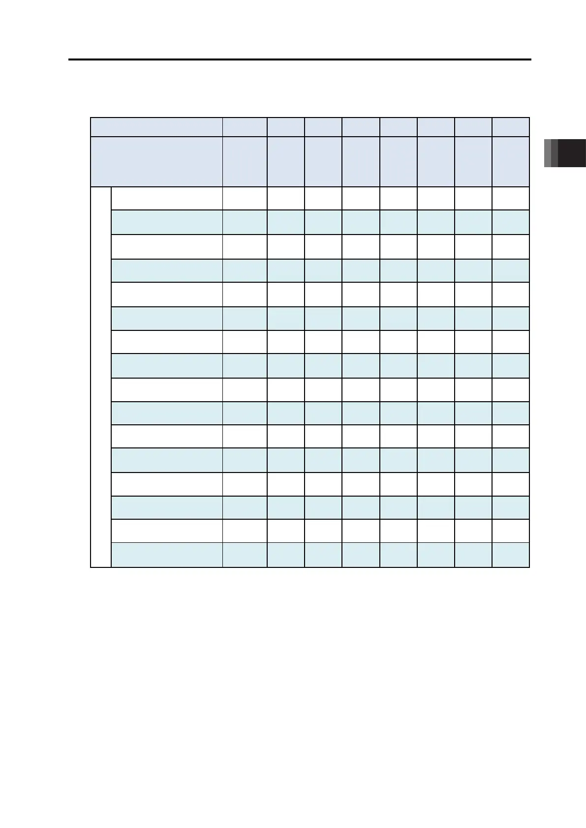
[2] List of Main Features in Each PIO Pattern
: Valid function
PIO Pattern
(Parameter No.25)
0 1 2 3 4 5 6 7
Mode
Mode
Mode
-
mode
-
mode
Valve
Mode 1
Valve
Mode 2
Sensor
Used
Sensor
Used
Major functions
Number of positioning points
64 64 256 512 7 3 32 5
Operation with the Position
× × ×
Position No. direct command
× × × × ×
Positioning
Velocity change during the
× × ×
Pressing (tension)
○ ×
Force Sensor Used Pressing
× × × × × ×
Pitch Feeding
×
Home return signal input
×
Pause
△
(Note 1)
Jog moving signal
× × × × × × ×
Teaching signal input
(Current Position Writing)
× × × × × × ×
Brake release signal input
×
Moving Signal Output
× × × × × ×
Zone signal output
(Note 2)
× × ×
Position zone signal output
(Note 3)
×
(Note 1) The pause signal is not provided. Refer to [4.2.7 [5].]
(Note 2) The zone range is set to the Parameters No.1 and 2 or No.23 and 24, and becomes
always effective after the home return is complete.
(Note 3) This feature is associated with the specified position number. The zone range is set in
the position table. The zone range is enabled only when the position is specified but
disabled if another position is specified. The pause signal is not provided.

 Loading...


