3. Wiring
3.1 Positioner Mode (PIO Control)
3-21
ME0342-4B
4) PIO Pattern 3 ············· 512-point mode (Number of positioning points : 512-point type)
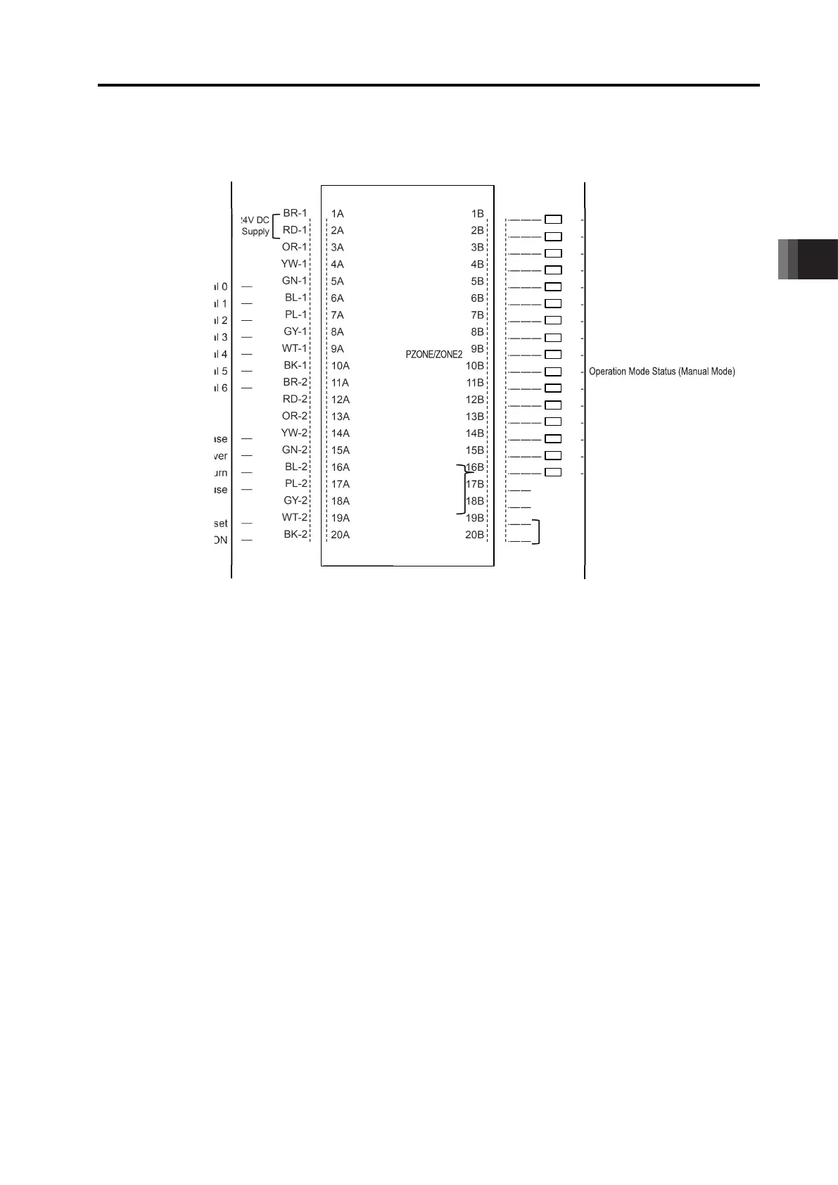
* in codes above shows the signal of the active low. Processing occurs when an
input signal of the type is turned OFF. An output signal of the type is normally ON
in the power-on status and turned OFF at signal output.
1B
2B
3B
4B
5B
6B
7B
8B
9B
10B
11B
12B
13B
14B
15B
16B
17B
18B
19B
20B
PM1 ――■
PM2 ――■
PM4 ――■
PM8 ――■
PM16 ――■
PM32 ――■
PM64 ――■
PM128 ――■
PM256 ――■
RMDS ――■
HEND ――■
PEND ――■
SV ――■
*EMGS ――■
*ALM ――■
24V DC (NPN Type)
0V (PNP Type)
No.256
Brake Control Release
Operation Mode Changeover
Home Return
Pause
Start
Reset
Servo ON
0V (NPN Type)
24V DC (PNP Type)
●――
●――
●――
●――
●――
●――
●――
●――
●――
●――
●――
●――
●――
●――
●――
●――
―――――(
―――――(
―――――(
―――――(
―――――(
―――――(
―――――(
―――――(
―――――(
―――――(
―――――(
―――――(
―――――(
―――――(
―――――(
―――――(
\
\
\
\
\
\
\
\
\
\
\
\
\
\
\
\
3.1 Positioner Mode (PIO Control)
ME0342-4B 3-22
5) PIO Pattern 4 ············ Solenoid Valve Mode 1 (7-point type)
* in codes above shows the signal of the active low. Processing occurs when an
input signal of the type is turned OFF. An output signal of the type is normally ON
in the power-on status and turned OFF at signal output.
1B
2B
3B
4B
5B
6B
7B
8B
9B
10B
11B
12B
13B
14B
15B
16B
17B
18B
19B
20B
PE0 ――■
PE1 ――■
PE2 ――■
PE3 ――■
PE4 ――■
PE5 ――■
PE6 ――■
ZONE1 ――■
――■
RMDS ――■
HEND ――■
PEND ――■
SV ――■
*EMGS ――■
*ALM ――■
LOAD
/TRQS
/*ALML
24V DC (NPN Type)
0V (PNP Type)
Start Signal
Start Signal
Start Signal
Start Signal
Start Signal
Start Signal
Start Signal
6
Brake Control Release
Operation Mode Changeover
Home Return
Pause
Reset
Servo ON
0V (NPN Type)
24V DC (PNP Type)
●――
●――
●――
●――
●――
●――
●――
●――
●――
●――
●――
●――
●――
-3
-3
-3
-3
-3
-3
-3
-3
-3
-3
-4
-4
-4
-4
-4
-4
-4
-4
-4
-4
BR-
RD-
OR-
YW-
GN-
BL-
PL-
GY-
WT-
BK-
BR-
RD-
OR-
YW-
GN-
BL-
PL-
GY-
WT-
BK-
No.0
No.1
No.2
No.3
No.4
No.5
No.6
rm
―――(
―――(
―――(
―――(
―――――(
―――――(
―――――(
―――――(
―――――(
―――――(
―――――(
―――(
―――(
―――――(
―――――(
―――――(
―――――(
―――(
―――――(
―――――(
\
\
\
\
\
\
\
\
\
\
\
\
\

 Loading...


