1: GENERAL INFORMATION
1-4 USER’S MANUAL
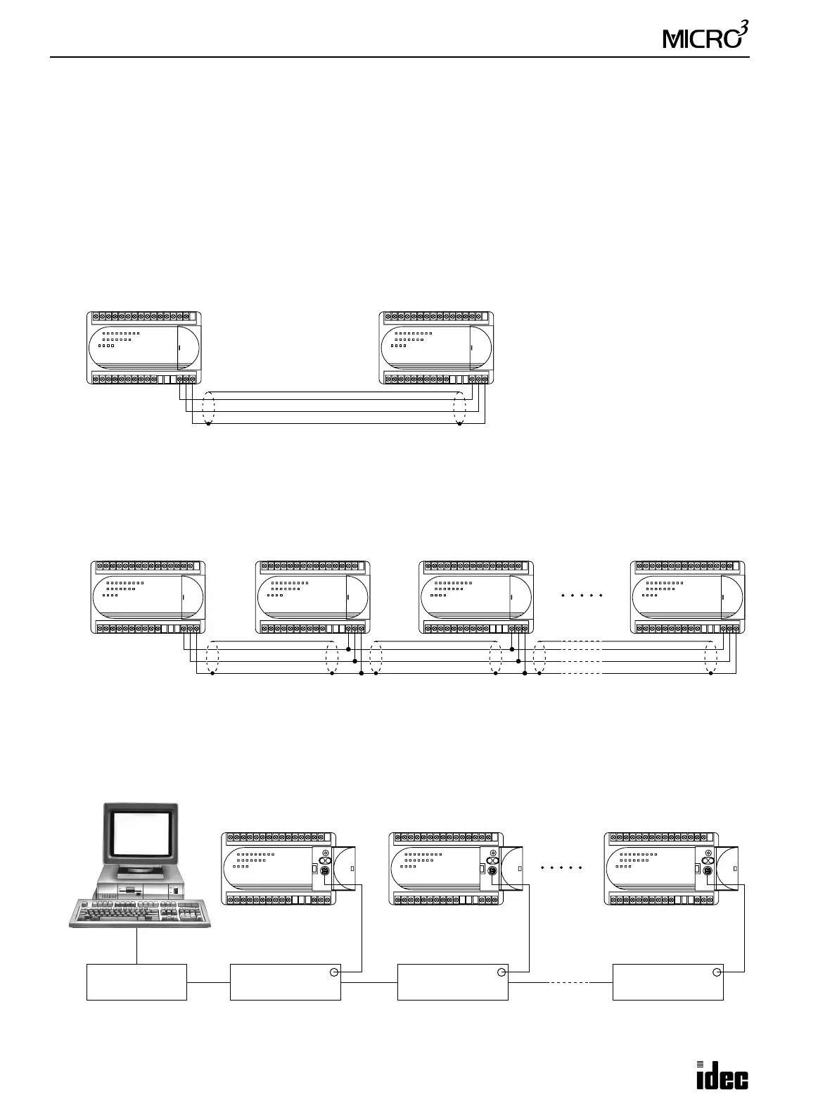
Link Systems
MICRO
3
has three link functions; expansion link, data link, and computer link. When using a link function, the function
selector switch may have to be set or the FUN settings may be required. For details of these settings, see Expansion Link
Function on page 4-6, Data Link Function on page 4-8, and Computer Link 1:N Communication on page 4-17. The expan-
sion link cannot be used in the data link system.
Expansion Link System
The expansion link system consists of two MICRO
3
base units connected through the data link terminals using the optional
expansion cable FC2A-KE1 (250 mm/9.84" long) or a shielded twisted pair cable as shown below. The cable for the
expansion link system can be extended up to 200 meters (656 feet). Every MICRO
3
base unit can be used as an expansion
station.
Data Link System
The data link system consists of one master station connected to a maximum of six slave stations to communicate control
data for distributed control. Every MICRO
3
base unit can be used as a master or slave station. When a slave station per-
forms communication at 19,200 bps through the loader port, multi-stage comparison instruction HSC1 cannot be used at
the slave station.
Computer Link System
In the computer link system, a personal computer is connected to one or a maximum of 32 MICRO
3
base units to control
the operation of all MICRO
3
base units. The 1:1 computer link system requires the computer link cable FC2A-KC2. The
1:N computer link system requires computer link interface unit FC2A-LC1 and RS232C/RS485 converter FC2A-MD1 in
addition to three types of cables.
Base Station Expansion Station
The RUN indicator on the expan-
sion station remains off whether the
base station is running or stopped.
Master Station Slave Station 1 Slave Station 2 Slave Station 6
Computer Link
Interface Unit
1st Unit
RS232C/RS485
Converter
Computer Link
Interface Unit
2nd Unit
Computer Link
Interface Unit
Nth Unit (N ≤ 32)
FC2A-MD1 FC2A-LC1 FC2A-LC1 FC2A-LC1