7: BASIC INSTRUCTIONS
USER’S MANUAL 7-15
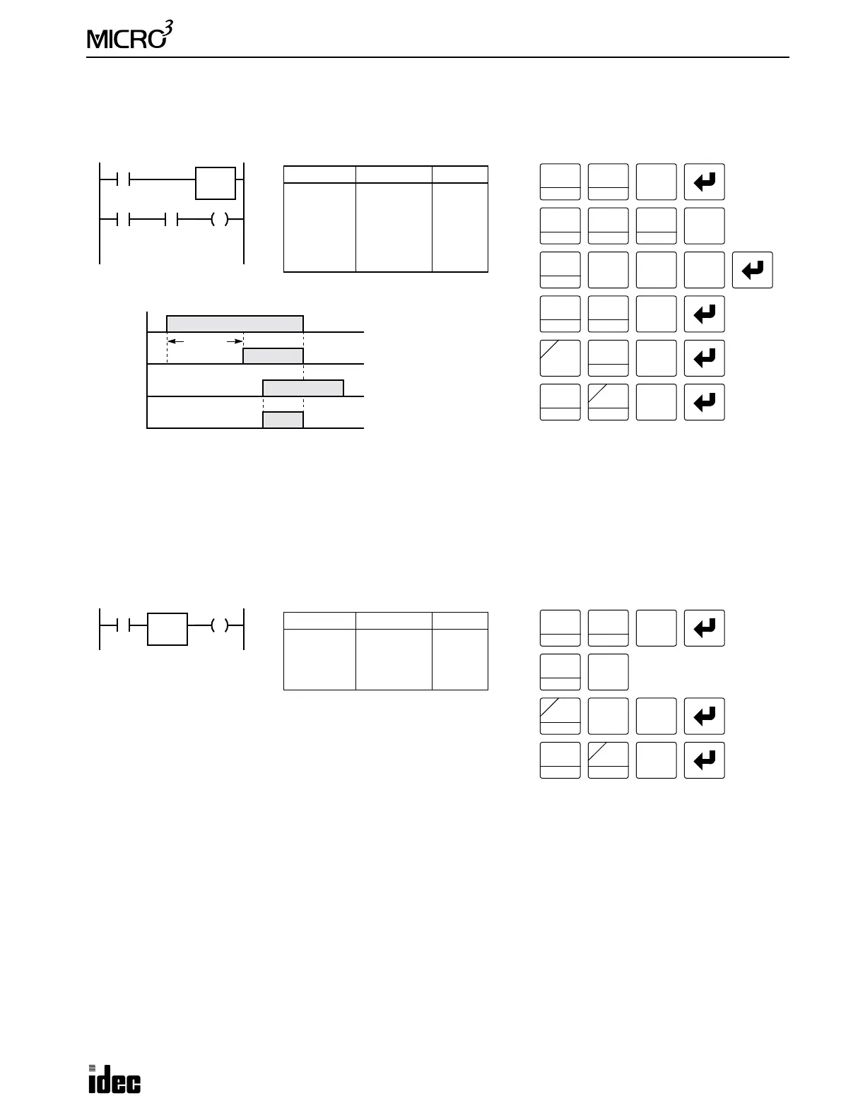
TIM, TMH, and TMS (Timer), continued
TMS (1-msec Timer)
Timer Circuit
The preset value 0 through 9999 can be designated using a data register D0 through D99 in the standard processing mode
or D0 through D31 in the high-speed processing mode; then the data of the data register becomes the preset value. Directly
after the TIM, TMH, or TMS instruction with two required addresses, the OUT (output) instruction can be keyed.
• Timedown from the preset value is initiated when the operation result
directly before the timer input is on.
• The timer output turns on when the timed value reaches zero.
• The timed value returns to the preset value when the timer input is off.
• The same timer or counter number cannot be programmed more than once. If an attempt is made to do so, then an error
message will result.
• Timer preset values can be changed without transferring the entire program to the MICRO
3
base unit again. See page
3-14. If the timer preset value is changed during timedown, then the timer remains unchanged for that cycle. The
change will be reflected in the next time cycle.
• If the timer preset value is changed to zero, then the timer stops operation, and the timer output is turned on immedi-
ately.
I5
I4
T2
Ladder Diagram (TMS)
Key Operation
LOD
10
SET
I
OUT
16
RST
F
Q
Prgm Adrs Instruction Data
0
1
3
4
5
LOD
TMS
LOD
AND
OUT
I4
2
100
I5
T2
Q2
Program List
I4
ON
OFF
T2
ON
OFF
I5
ON
OFF
Q2
ON
OFF
Timing Chart
LOD
10
SET
I
AND
D
TS2
100
Q2
TIM
T
1
BPS
0
LOD
10
TIM
T
0.1 sec
2
BRD
TIM
T
0
5
CC=
4
TIM
T
2
BRD
2
BRD
Note: Pressing the TIM key on the pro-
gram loader programs the TIM, TMH, or
TMS instruction alternately.
I1
Ladder Diagram
Key Operation
LOD
10
SET
I
OUT
16
RST
F
Q
Prgm Adrs Instruction Data
0
1
3
LOD
TIM
OUT
I1
5
D10
Q0
Program List
T5
D10
Q0
TIM
T
1
BPS
0
5
CC=
OR
E
D
1
BPS
0