7: BASIC INSTRUCTIONS
7-16 USER’S MANUAL
Timer Accuracy
Timer accuracy due to software configuration depends on three factors: timer input error, timer counting error, and timeout
output error. These errors are not constant but vary with the user program and other causes.
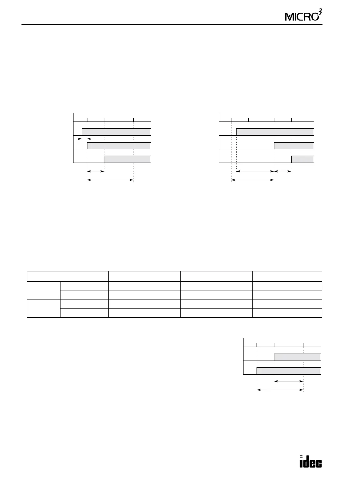
Timer Input Error
The input status is read at the END processing and stored to the input RAM. So, an error occurs depending on the timing
when the timer input turns on in a scan cycle. The same error occurs on the normal input and the catch input. The timer
input error shown below does not include input delay caused by the hardware.
Timer Counting Error
Every timer instruction operation is individually based on asynchronous 16-bit reference timers. Therefore, an error occurs
depending on the status of the asynchronous 16-bit timer when the timer instruction is executed.
Timeout Output Error
The output RAM status is set to the actual output when the
END instruction is processed. So, an error occurs depend-
ing on the timing when the timeout output turns on in a scan
cycle. The timeout output error shown on the right does not
include output delay caused by the hardware.
Timeout output error is equal to Tte (behind error) and can
be between zero and one scan time.
0 < Tte < 1 scan time
Tte: Time from the timer instruction execution to the END processing
Error TIM (100-msec timer) TMH (10-msec timer) TMS (1-msec timer)
Minimum
Advance error 0 msec 0 msec 0 msec
Behind error 0 msec 0 msec 0 msec
Maximum
Advance error 100 msec 10 msec 1 msec
Behind error 1 scan time 1 scan time 1 scan time
Program Processing
Actual Input
ON
OFF
Input RAM
ON
OFF
Timer Start
Minimum Error
Tie
END
1 scan time
TIM END
Tet
Program Processing
Actual Input
ON
OFF
Input RAM
ON
OFF
Timer Start
Maximum Error
END
1 scan time
TIM END
Tet
TIM
Tie
When the input turns on immediately before the
END processing, Tie is almost zero. Then the
timer input error is only Tet (behind error) and is
at its minimum.
When the input turns on immediately after the END
processing, Tie is almost equal to one scan time. Then
the timer input error is Tie + Tet = one scan time + Tet
(behind error) and is at its maximum.
Tie: Time from input turning on to the END processing
Tet: Time from the END processing to the timer instruction execution
Program Processing
Timeout Output RAM
ON
OFF
Actual Output
ON
OFF
END
1 scan time
TIM END
Tte