7: BASIC INSTRUCTIONS
USER’S MANUAL 7-17
Timer Accuracy, continued
Maximum and Minimum of Individual Errors
Maximum and Minimum of Total Error
Tet + Tte = 1 scan time
Power Failure Memory Protection
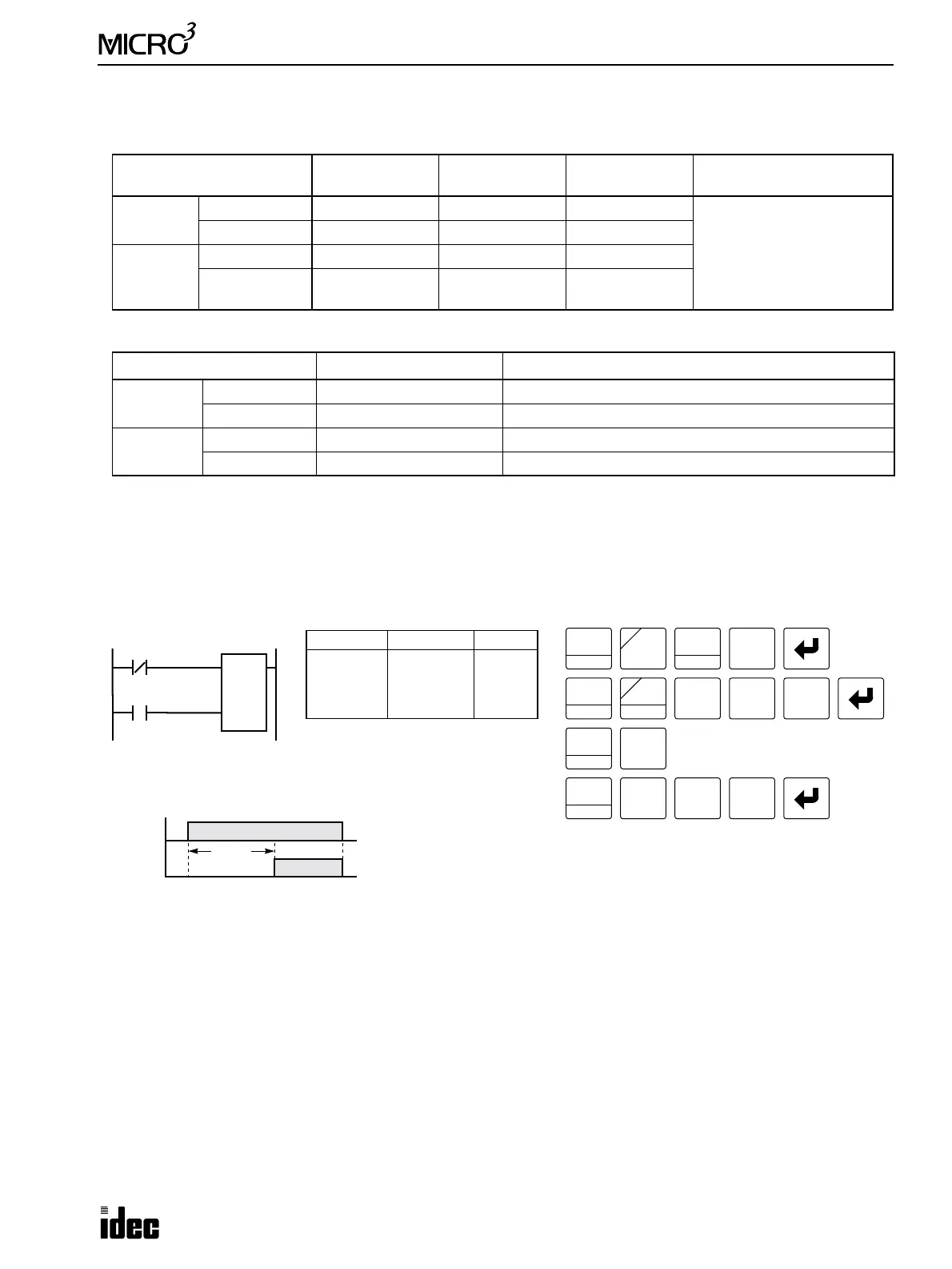
Timers TIM, TMH, and TMS do not have power failure protection. A timer with this protection can be devised using a
counter instruction and special internal relay M311 (1-sec clock), M312 (100-msec clock), or M313 (10-msec clock).
Error
Timer
Input Error
Timer Counting
Error
Timeout Output
Error
Remarks
Minimum
Advance error 0 (Note) 0 0 (Note)
Note:
Advance error does not
occur at the timer input and
timeout output. Increment is
100 msec (TIM), 10 msec
(TMH), or 1 msec (TMS).
Behind error Tet 0 Tte
Maximum
Advance error 0 (Note) Increment 0 (Note)
Behind error
1 scan time
+ Tet
1 scan time Tte
Error Total Error Remarks
Minimum
Advance error 0
Behind error 0
Maximum
Advance error Increment – (Tet + Tte) The maximum advance error is: Increment – 1 scan time
Behind error 2 scan times + (Tet + Tte) The maximum behind error is: 3 scan times
M312
Ladder Diagram
Key Operation
LOD
10
SET
I
Prgm Adrs Instruction Data
0
1
2
LOD NOT
LOD
CNT
I1
M312
2
100
Program List
LOD
10
C2
100
LOD
10
Note: Counters CNT2 through CNT31 are adding counters, and all counter
current values are maintained during a power failure.
2
BRD
2
BRD
I1
NOT
A
SOT
C
M
3
BPP
1
BPS
CNT
C
1
BPS
0 0
1
BPS
Reset
Pulse
I1
ON
OFF
C2
ON
OFF
Timing Chart
10 sec
(100-msec Timer)