7: BASIC INSTRUCTIONS
7-24 USER’S MANUAL
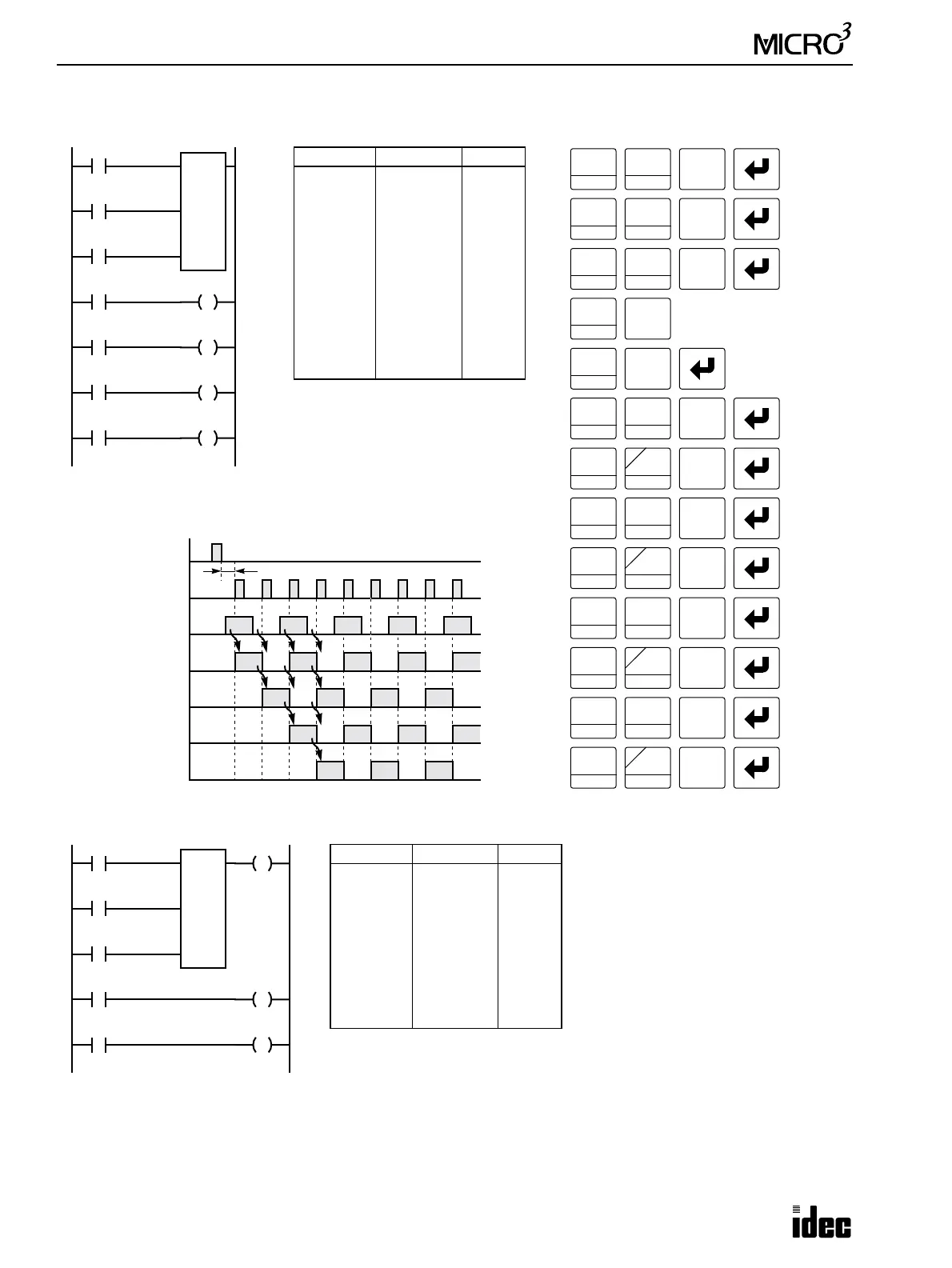
Forward Shift Register (SFR), continued
I1
I0
Ladder Diagram
Key Operation
LOD
10
SET
I
Prgm Adrs Instruction Data
0
1
2
3
5
6
7
8
9
10
11
12
LOD
LOD
LOD
SFR
LOD
OUT
LOD
OUT
LOD
OUT
LOD
OUT
I0
I1
I2
0
4
R0
Q0
R1
Q1
R2
Q2
R3
Q3
Program List
R0
4
1
BPS
0
Reset
Pulse
LOD
10
SET
I
LOD
10
Reset Input I0
ON
OFF
Pulse Input I1
ON
OFF
Data Input I2
ON
OFF
Timing Chart
R1
ON
OFF
One scan or more is required
R0
2
BRD
ON
OFF
0
I2
Data
LOD
10
SET
I
SFR
R
4
R3
ON
OFF
R2
ON
OFF
R0
R1
R2
R3
LOD
10
SFR
R
0
OUT
16
RST
F
Q
0
LOD
10
SFR
R
OUT
16
RST
F
Q
LOD
10
SFR
R
OUT
16
RST
F
Q
LOD
10
SFR
R
OUT
16
RST
F
Q
1
BPS
1
BPS
2
BRD
2
BRD
3
BPP
3
BPP
Q0
Q1
Q2
Q3
I2
I1
Ladder Diagram
Prgm Adrs Instruction Data
0
1
2
3
5
6
7
8
9
LOD
LOD
LOD
SFR
OUT
LOD
OUT
LOD
OUT
I1
I2
I3
0
4
Q3
R0
Q0
R1
Q1
Program List
R0
4
Reset
Pulse
I3
Data
Q3
R0
R1
Q0
Q1
• The last bit status output can be
programmed directly after the SFR
instruction with two required
addresses is keyed. In this example,
the status of bit R3 is read to output
Q3.
• Each bit can be loaded using the
LOD SFR R# instructions.