7: BASIC INSTRUCTIONS
USER’S MANUAL 7-31
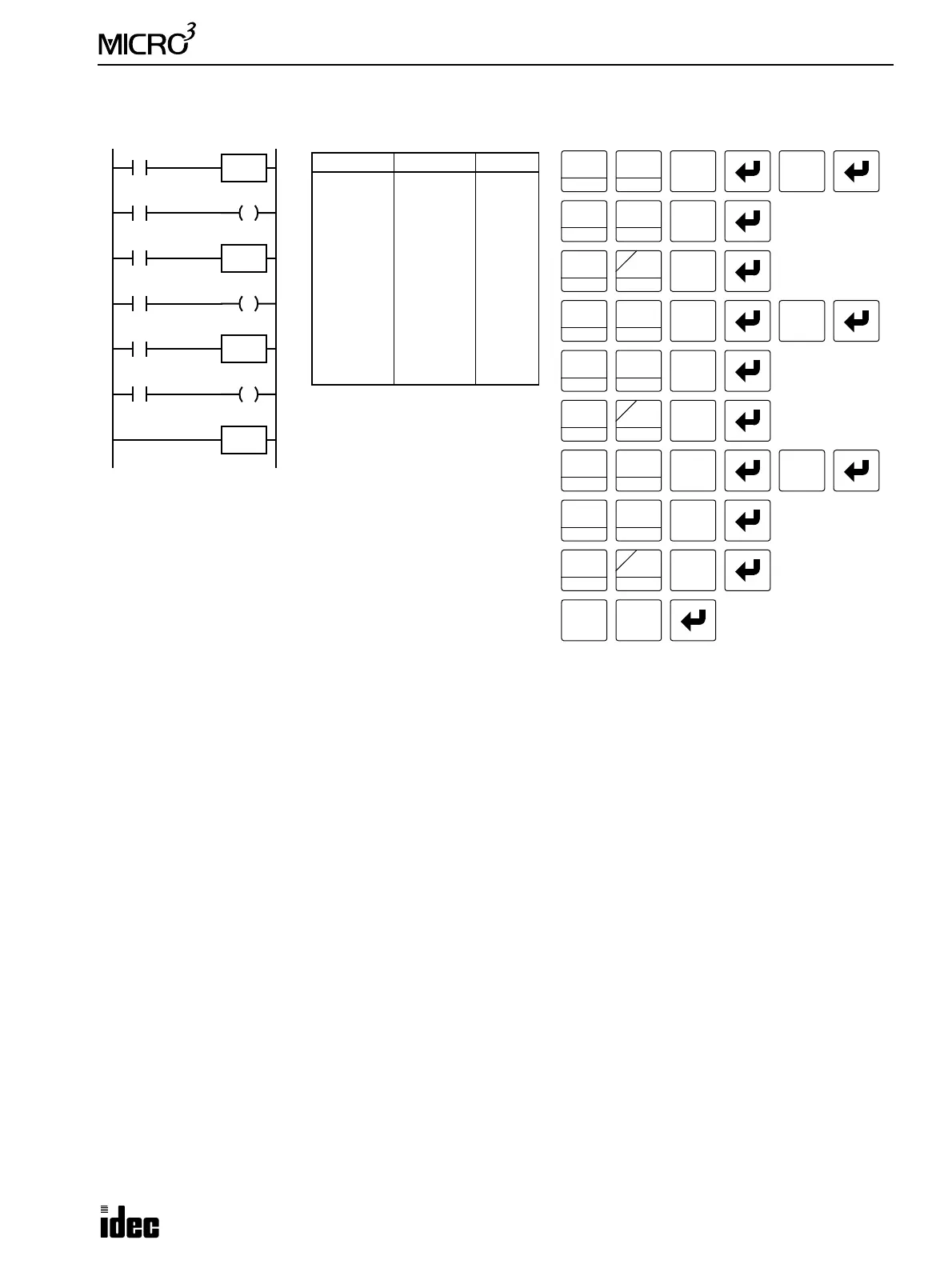
JMP (Jump) and JEND (Jump End), continued
Ladder Diagram
Key Operation
I1
LOD
10
Prgm Adrs Instruction Data
0
1
2
3
4
5
6
7
8
9
10
11
12
LOD
JMP
LOD
OUT
LOD
JMP
LOD
OUT
LOD
JMP
LOD
OUT
JEND
I1
I2
Q0
I3
I4
Q1
I5
I6
Q2
Program List
OUT
16
RST
F
Q
0
2
BRD
Q0
I2
I3
I4
I5
I6
JMP
JEND
JMP
JMP
Q1
Q2
SET
I
1
BPS
LOD
10
SET
I
LOD
10
OUT
16
RST
F
Q
2
BRD
SET
I
1
BPS
LOD
10
SET
I
6
CC>=
3
BPP
5
CC=
4
LOD
10
OUT
16
RST
F
Q
SET
I
LOD
10
SET
I
This jump circuit will give priority to I1, I3, and I5, in that order.
When input I1 is on, the first JMP is executed so that subsequent
output statuses of Q0 through Q2 are held.
When input I1 is off, the first JMP is not executed so that the fol-
lowing program is executed according to the actual input statuses of
I2 through I6.
When I1 is off and I3 is on, the second JMP is executed so that sub-
sequent output statuses of Q1 and Q2 are held.
When both I1 and I3 are off, the first and second JMP’s are not exe-
cuted so that the following program is executed according to the
actual input statuses of I4 through I6.
9
JMP/E
9
JMP/E
9
JMP/E
9
JMP/E
9
JMP/E