12: BOOLEAN COMPUTATION INSTRUCTIONS
12-2 USER’S MANUAL
Valid Operands (Standard Processing)
In the high-speed processing mode, operands for advanced instructions are limited. See page 6-1.
When T (timer) or C (counter) is used as S1 or S2, the timer/counter current value is read out. When T (timer) or C
(counter) is used as D1, the data is written in as a preset value which can be 0 through 9999.
Note: When using the timer or counter as destination, make sure that the data does not exceed the maximum preset value
of 9999. When the preset value exceeds 9999, a user program execution error will result, turning on error indicator ERR1
and special internal relay M304. When a user program execution error occurs, the result is not set to the destination.
Since these Boolean instructions are executed in each scan while input is on, a pulse input from an SOTU or SOTD
instruction should be used as required.
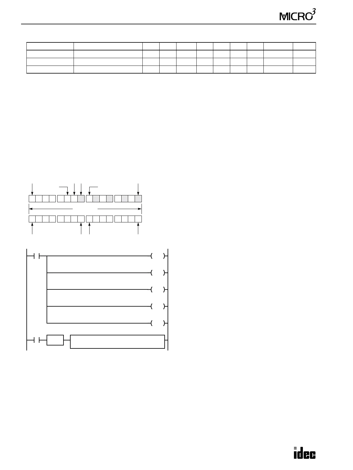
Example: XORW
To convert optional output status among a series of 10 output points, use the XORW instruction in combination with 10
internal relay points.
Operand Function I Q M T C R D Constant Repeat
S1 (Source 1) Data for computation 0-35 0-31 0-317 0-31 0-31 0-63 0-99 0-65535 1-31
S2 (Source 2) Data for computation 0-35 0-31 0-317 0-31 0-31 0-63 0-99 0-65535 1-31
D1 (Destination 1) Destination to store results — 0-31 0-287 0-31 0-31 0-63 0-99 — 1-31
M301
M0
SET
Ten points of outputs Q0 through Q11 are assigned to 10
points of internal relays M0 through M11.
Five points of M0, M2, M4, M6, and M10 are set by ini-
tialize pulse special internal relay M301.
When input I1 is turned on, the XORW instruction is
executed to invert the status of outputs Q0, Q2, Q4, Q6,
and Q10.
0 0 00 0 0 1 10 0 1 0 1 0 1 0
Q0
Q7
Q10Q11
Q12
Q17
16 points
This program will invert the status of the shaded outputs at the
left from on to off, and those not shaded from off to on.
This example uses the 24-I/O type MICRO
3
base unit, which has
10 output terminals Q0 through Q7, Q10, and Q11.
XORW REP
**
S1
M0
S2
Q0
D1
Q0
SOTU
I1
M2
SET
M4
SET
M6
SET
M10
SET
M0M7M10M17