1: GENERAL INFORMATION
1-10 USER’S MANUAL
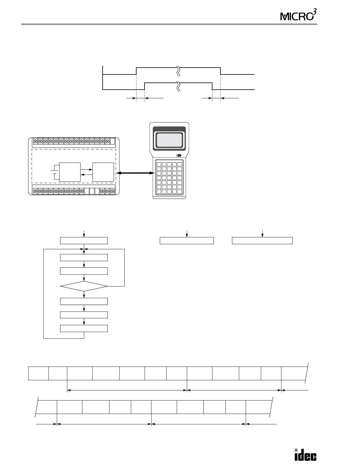
Power Supply Timing Chart
Turn on AC or DC main power and I/O power at the same time, or turn on AC or DC main power first.
Turn off AC or DC main power and I/O power at the same time, or turn off I/O power first.
Memory Backup Function
Self-diagnostics Flow Chart
Scanning Process and WDT (Watch Dog Timer)
I/O Power
ON
OFF
≥ 0 sec
AC/DC Main Power
ON
OFF
≥ 0 sec
PLC Memory
RAM EEPROM
Battery
Program
Data
Program
The user program and data stored in the RAM
are backed up by a lithium secondary battery.
When the contents in the RAM are destroyed
after a power failure longer than the specified
value, the user program is transferred from the
EEPROM to the RAM at power up automati-
cally, so the user memory is not erased. Since
the data is destroyed, an error message, such as
keep data sum check error, is evoked to alert
the user.
Power ON
System Initialization
Internal Processing A
Read Inputs
RUN or STOP
Internal Processing B
Execute Program
Update Outputs
STOP
RUN
Interrupt
Loader Communication
Interrupt
Data Link Communication
Power ON
Initialize
System
Processing A
Read Inputs
Determination
RUN
Internal
Processing B
Execute
Program
Update
Outputs
Scan 1
Processing A
Read Inputs
Determination
RUN
Execute
Program
Update
Outputs
Processing A
Read Inputs
Update
Outputs
Processing A
Read Inputs
Determination
RUN
Execute
Program
Update
Outputs
Processing A
Read Inputs
Determination
RUN
Execute
Program
Update
Outputs
Scan 2 Scan 3
Scan N–1 Scan N Scan N+1 Scan N+2
Processing A
Read Inputs
When the scan time is longer than the WDT preset value (300 msec), error indicator ERR1 flashes and the PLC stops operation.