15: INTERFACE INSTRUCTIONS
15-2 USER’S MANUAL
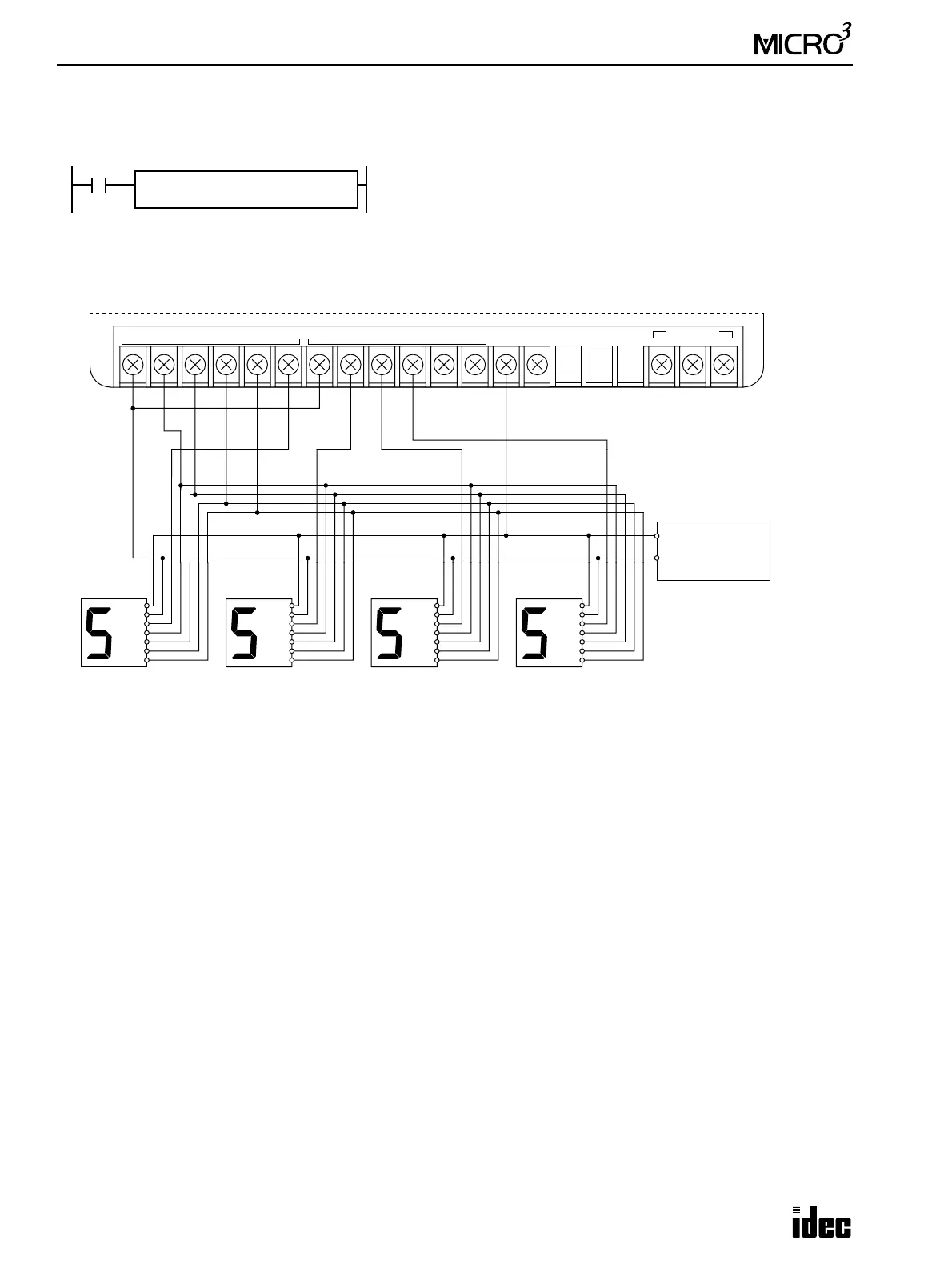
Example: DISP
The following example demonstrates a program to display the 4-digit current value of counter CNT10 on display units
connected to the 24-I/O transistor sink output type MICRO
3
base unit.
Output Wiring Diagram
When input I0 is on, the 4-digit current value of counter C10 is dis-
played on 7-segment digital display units.
I0
DISP DAT
BCD4
LAT
LL
S1
C10
Q
Q0
(+)
(–)
Latch
A
B
C
D
(+)
(–)
24V DC
Power
Supply
(+)
(–)
Latch
A
B
C
D
(+)
(–)
Latch
A
B
C
D
(+)
(–)
Latch
A
B
C
D
10
0
10
1
10
2
10
3
OUT
COM0(–)
0123 NC
DATA LINK
ASGB
+V4
OUT
COM1(–)
5 6 7 10 11
MICRO
3
Base Unit FC2A-C24B1 (Transistor Sink Output)
Lower Digit Upper Digit