APPENDIX
A-4 USER’S MANUAL
Type List, continued
Cables and Accessories
AC Adapter
When using the program loader for off line programming or communication with a computer, an AC adapter is required to
power the program loader. AC adapter output capacity: 5 to 6.5V DC, 4W
The RS232C/RS485 converter is powered by 24V DC source or
an AC adapter with 9V DC, 350mA output capacity.
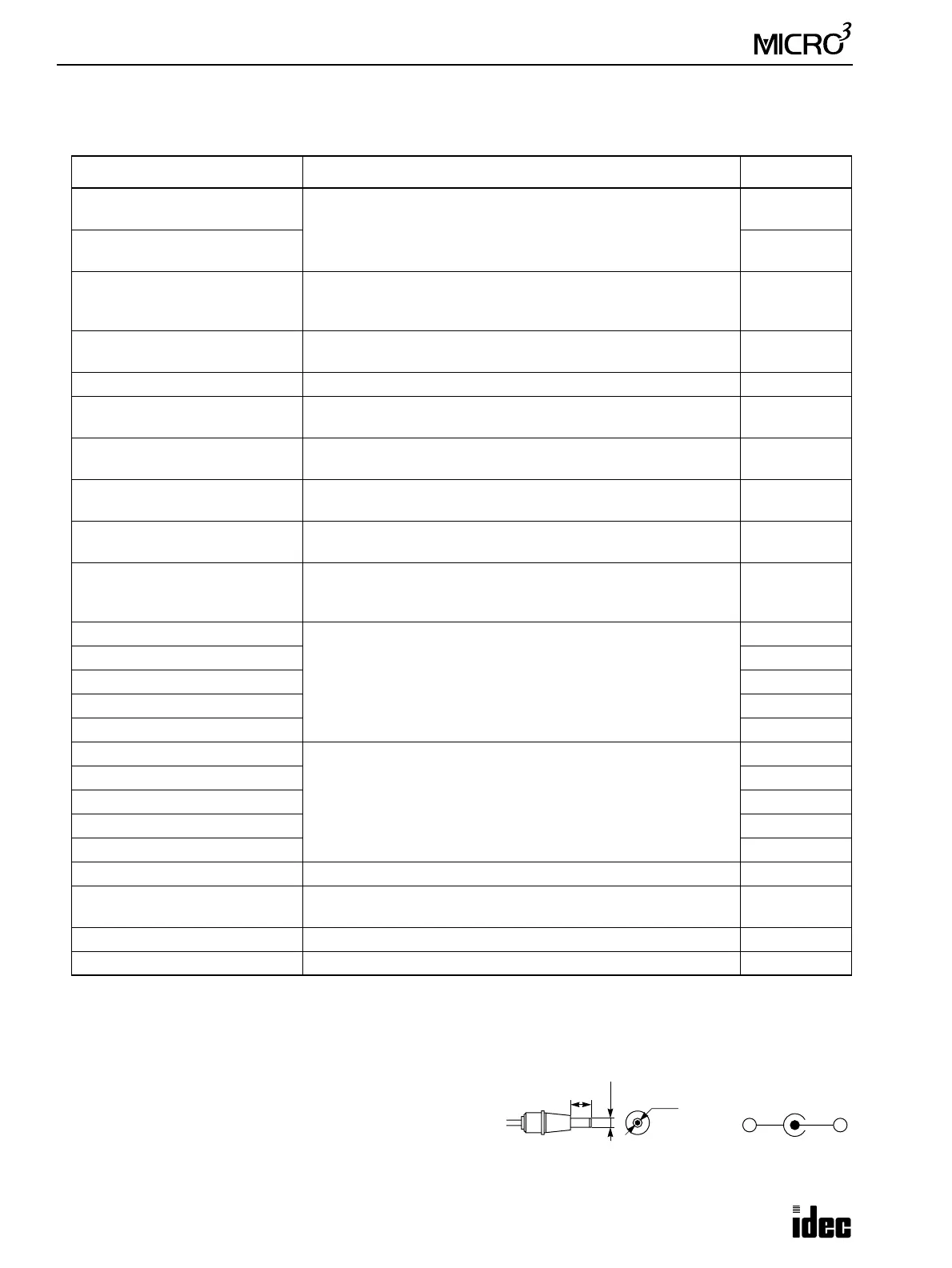
The output plug of the AC adapter applicable to both the program
loader and RS232C/RS485 converter is shown on the right.
Name Function Type No.
Loader Cable 1 (2m/6.56 ft.
long)
Used to connect the program loader to the
MICRO
3
base unit
(Loader cable is not included with program loader.)
FC2A-KL1
Loader Cable 2 (5m/16.4 ft.
long)
FC2A-KL2
Computer Link Cable
Used to connect the MICRO
3
base unit or program loader to IBM
PC (in the 1:1 computer link system), 2m (6.56 ft.) long, with D-
sub 9-pin female connector to connect to computer
FC2A-KC2
Jack Converter (included with
computer link cable)
Used on the computer link cable to connect an AC adapter to
power the program loader connected to IBM PC
FC2A-CJ1
Memory Card SRAM memory card to store 31 user programs max. (64K bytes) FC2A-MC1
Expansion Cable
Used to connect MICRO
3
base units for close mounting in the
expansion link system, 250mm (9.84") long
FC2A-KE1
Computer Link Interface Unit
Used to connect MICRO
3
base unit to the RS232C/RS485
converter in the 1:N computer link system
FC2A-LC1
Computer Link Interface Cable
Used to connect MICRO
3
base unit to the computer link interface
unit in the 1:N computer link system, 100 mm (3.937”) long
FC2A-KC3
RS232C/RS485 Converter
Used to connect the computer link interface unit to IBM PC in the
1:N computer link system
FC2A-MD1
RS232C Cable (4-wire)
Used to connect the RS232C/RS485 converter to IBM PC in the
1:N computer link system, 1.5m (4.92 ft.) long, with D-sub 9-pin
female connector to connect to computer
HD9Z-C52
A/D Converter Unit 1 (0 to 5V)
Used to convert an analog signal to a digital signal and send it to
input I0 of the MICRO
3
base unit
(Resolution: 8 bits)
FC2A-AD1
A/D Converter Unit 2 (0 to 10V) FC2A-AD2
A/D Converter Unit 3 (±5V) FC2A-AD3
A/D Converter Unit 4 (4 to 20mA) FC2A-AD4
A/D Converter Unit 5 (±10V) FC2A-AD5
D/A Converter Unit 1 (0 to 5V)
Used to convert a digital signal (PWM signal) from output Q0 of the
MICRO
3
base unit to an analog signal
(Resolution: 8 bits)
FC2A-DA1
D/A Converter Unit 2 (0 to 10V) FC2A-DA2
D/A Converter Unit 3 (±5V) FC2A-DA3
D/A Converter Unit 4 (4 to 20mA) FC2A-DA4
D/A Converter Unit 5 (±10V) FC2A-DA5
Analog Timer Unit To set timer preset value externally (See page 4-20 – accessories.) PFA-1U11
DIN Rail
35-mm-wide DIN rail to mount MICRO
3
base unit, 1m (3.28 ft.)
long
BAA1000
Mounting Clip Used on DIN rail to fasten the MICRO
3
base unit BNL6
CUBIQ Programming and monitoring software used on PC (3.5" diskette) FC9Y-LP1E314
◆ For the MICRO
C, see the MICRO
C User’s Manual. ◆
9.5
ø2.1
ø5.5
Polarity
+
–
Dimensions in mm.