2: OPERATION BASICS
USER’S MANUAL 2-5
Transfer Program and Monitor MICRO
3
Operation
Transfer the program to the MICRO
3
base unit, run the program and monitor the operation using the program loader using
the following procedures.
Press the TRS key on the program loader to select the transfer mode.
The program loader displays as shown on the right:
Press the key. The display changes as shown on the right.
Press the key again to start program transfer. When program trans-
fer is completed, the display changes as shown on the right.
To run the program on the MICRO
3
base unit, set the RUN/STOP
switch on the program loader to RUN. See that the RUN indicator on
the MICRO
3
base unit is turned on.
Monitor the input and output operation referring to the time chart on
the preceding page.
When input I0 is turned on (IN0 indicator on), output Q0 is turned on
(OUT0 indicator on).
When input I0 is turned off (IN0 indicator off), output Q0 remains on.
When input I1 is turned on (IN1 indicator on), output Q1 is turned on
(OUT1 indicator on).
When input I1 is turned off (IN1 indicator off), output Q1 remains on.
When input I2 is turned on (IN2 indicator on), both outputs Q0 and Q1
are turned off (OUT0 and OUT1 indicators off).
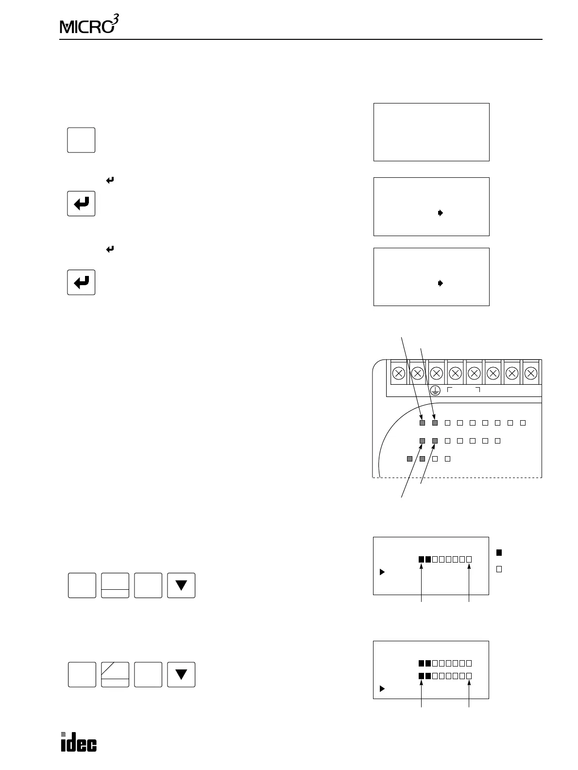
The I/O operation can also be monitored using the program loader.
Press the MON key on the program loader to select the monitor mode.
Then, enter the operand and number to monitor. To monitor input I0,
press keys:
Eight points are monitored starting with the selected number. The pro-
gram loader displays changes as shown on the right.
To monitor 8 output points starting with output Q0 on the program
loader, press keys:
TRS 1Kstep
Loader••••PC
TRS
TRS 1Kstep
(Write)
Loader PC
OK?
TRS 1Kstep
(Write)
Loader PC
END
100-240V AC
LN
DC OUT
24V 0V
DC IN
COM
01
IN
0
123456710
OUT0123456
POW RUN ERR1 ERR2
Remains on while output Q0 is on.
Remains on while output Q1 is on.
Remains on while input I1 is on.
Remains on while input I0 is on.
MON
0
SET
I
MON
0
RST
F
Q