3: PROGRAM LOADER
3-18 USER’S MANUAL
Setting and Resetting
Inputs, outputs, internal relays, and shift register bits can be temporarily turned on (SET) or turned off (RST), using the
program loader.
Inputs and outputs can be set or reset only while the MICRO
3
base unit is running. The designated input or output is set or
reset at the first execution of the END instruction after the key is pressed. After executing the END instruction, the input
reflects the actual input, and the output is operated according to the existing program.
Internal relays and shift register bits can be set or reset whether the MICRO
3
base unit is running or not. When setting or
resetting internal relays or shift register bits, the on or off status becomes in effect as soon as the key is pressed. If the
internal relay or shift register bit is designated with “keep” status, then the set or reset operation remains in effect after the
MICRO
3
base unit is tuned on. For “keep” designation, see FUN3 on page 5-4 and FUN4 on page 5-5.
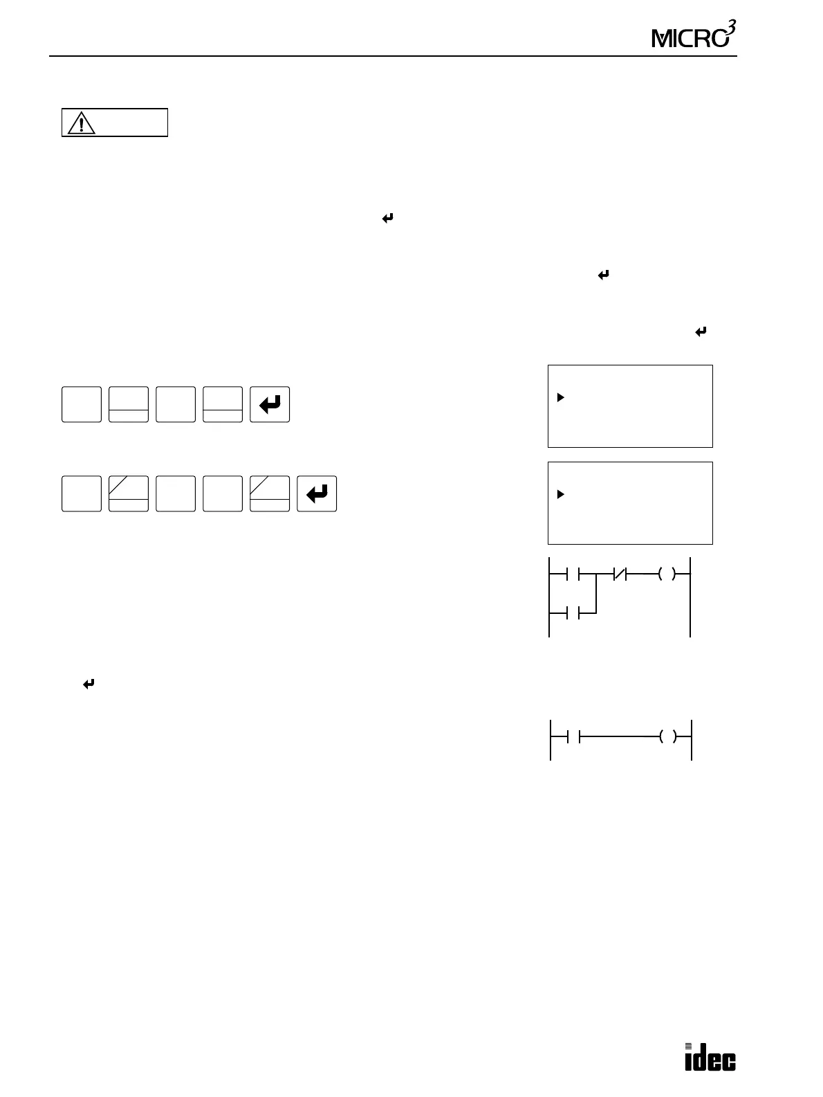
To set or reset an operand, press the MON key, the operand and number, followed by the SET or RST key, and the key.
When the operand is correctly set or reset, “OK” is displayed. If not, the program loader will beep.
Example: Set input I1
When the input is set correctly, “OK” is displayed.
Example: Reset internal relay M10
When reset correctly, “OK” is displayed.
When input I1 is turned on (SET), the circuit on the right will be actuated to hold
output Q0. If the NC input I2 is turned off using the SET operation, the circuit
will return to its non-actuated status.
Timing for SET and RST Operation
The SET or RST operation is set to the MICRO
3
base unit RAM when the first END instruction is executed after pressing
the key. The subsequent sequence is executed according to the user program. Inputs are updated depending on actual
external inputs. Outputs, internal relays, and shift registers are updated according to the user program.
In the END execution, the processing occurs on actual output processing, actual
input processing, and SET/RST processing in this order. When input I1 is turned
on using the SET operation in the program on the right while the actual external
input remains off, the result is reflected as follows.
If input I1 is set using the SET operation in the 100th scan, input I1 in the RAM is turned on in the 101st scan, which turns
output Q1 in the RAM on. As a result, actual output Q1 is turned on when the END instruction is executed in the 101st
scan. Since actual input I1 is off in the 102nd scan, I1 and Q1 in the RAM are turned off. Consequently, actual output Q1
is turned off when the END instruction is executed in the 102nd scan. See the timing chart on the next page.
Caution
• Make sure of safety when operating the MICRO
3
to force outputs on (SET) or off (RST). Incorrect
operation on the MICRO
3
may cause machine damage or accidents.
MON
MON
I 1 SET -OK-
SET
I
1
BPS
SET
I
MON
MON
M 10 RST -OK-
1
BPS
RST
F
Q
SOT
C
M
0
I1
I2 Q0
Q0
I1
Q1