4: SPECIAL FUNCTIONS
4-10 USER’S MANUAL
Operating Procedure for Data Link System
To set up and use a data link system, complete the following steps:
First determine the assignments for the master station and slave stations.
Connect
MICRO
3
base units at the master station and all slave stations as illustrated on page 4-8.
Set the function selector switch to 0 on the MICRO
3
base unit at the master station and to 1 through 6 at slave stations.
Create user programs for the master and slave stations. Different programs are used for the master and slave stations.
Power up every
MICRO
3
base unit at the same time, and transfer the user programs to the master and slave stations.
Monitor the data registers used for data link at the master and slave stations.
Note: To enable data link communication, power up every MICRO
3
base unit at the same time, or power up slave stations
first. If a slave station is powered up later than the master station, the master station does not recognize the slave station. To
recognize the slave station in this case, execute FUN27 Link Formatting Sequence at the master station (see page 5-11) or
turn on M307 Link Communication Initialize Flag at the master station (see page 6-3).
The scan time is extended by approximately 12 msec in the data link system.
If any communication error occurs in the data link system, link communication error codes are set to data register D85 at
the slave station and to a corresponding data register for link communication error at the master station. For details of link
communication error codes, see page 18-5. To enable control data register D94 for link communication error code, use
FUN10 Control Data Register Setting. See page 5-8. If a communication error occurs, the data is resent three times. If the
error still exists after three attempts, then the error code is set to the data registers for link communication error. Since the
error code is not communicated between the master and slave stations, error codes must be cleared individually.
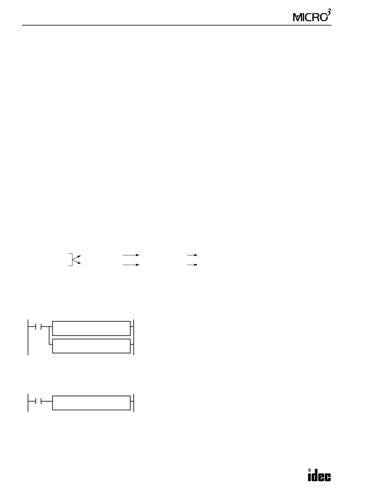
Data Link Example 1: Data Transmission from Master Station
This example demonstrates data communication from the master station to two slave stations. Data of inputs I0 through I7
and I10 through I17 are set to data registers D61 (transmission data H for slave station 1) and D66 (transmission data H for
slave station 2) at the master station. D61 data is sent to D88 (receive data H) of slave station 1, and D66 data is sent to
D88 (receive data H) of slave station 2.
Function selector switch setting
Master station: 0
Slave station 1: 1
Slave station 2: 2
Master station program
Slave station program
The same program is used for slave stations 1 and 2 in this example.
Note: The MOV (move) instruction moves 16-bit word data from the source operand to the destination operand. Although
16-bit word data is processed internally, data cannot be read from or written to non-existent terminals When using the 24 I/
O type MICRO
3
base unit which has 14 input terminals and 10 output terminals, data of only 14 input points I0 through I15
can be read to data register D61 and D66 at the master station and the upper two bits are set to zero in the data registers.
Data of data register D88 can be taken out from only lower 10 output points Q0 through Q11 at the slave stations and the
upper 6 outputs Q12 through Q17 cannot be taken out.
Master Station Slave Stations
I0 through I7
I10 through I17
D61 (Trans. H)
D66 (Trans. H)
D88 (Receive H)
D88 (Receive H)
Q0 through Q7, Q10 through Q17 (Slave Station 1)
Q0 through Q7, Q10 through Q17 (Slave Station 2)
M317
MOV REP
**
M317 is the in-operation output special internal relay which remains on dur-
ing operation.
The first MOV (move) instruction sets 16 inputs I0 through I7 and I10
through I17 to data register D61 (transmission data H for slave station 1).
The second MOV (move) instruction sets 16 inputs I0 through I7 and I10
through I17 to data register D66 (transmission data H for slave station 2).
S1
I0
D1
D61
MOV REP
**
S1
I0
D1
D66
M317
MOV REP
**
The MOV (move) instruction sets the data of data register D88 (receive data
H) to 16 outputs Q0 through Q7 and Q10 through Q17.
S1
D88
D1
Q0