4: SPECIAL FUNCTIONS
USER’S MANUAL 4-11
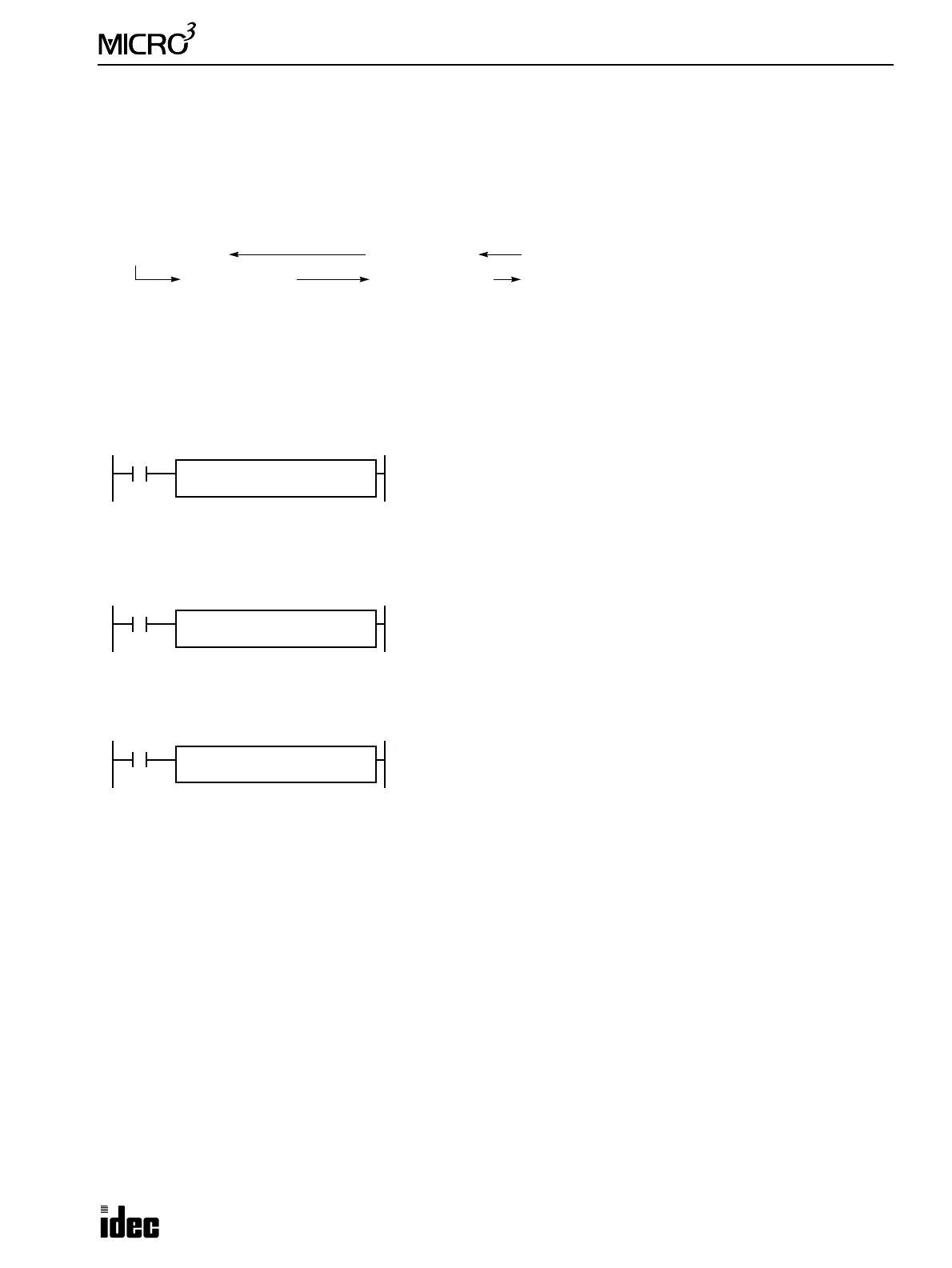
Data Link Example 2: Data Transmission from Slave Station
This sample program demonstrates data communication from slave station 1 to the master station, then to slave station 2.
Data of inputs I0 through I7 and I10 through I17 are set to data register D86 (transmission data H) at slave station 1. The
D86 data is sent to data register D63 (receive data H for slave station 1) of the master station. At the master station, D63
data is moved to data register D66 (transmission data H for slave station 2). The D66 data is sent to data register D88
(receive data H) of slave station 2, where the D88 data is set to outputs Q0 through Q7 and Q10 through Q17.
Function selector switch setting
Master station: 0
Slave station 1: 1
Slave station 2: 2
Master station program
Slave station 1 program
Slave station 2 program
Data Link Example 3: Input and Counter Data Transmission
This sample program demonstrates a data link system to transmit input and counter data between the master station and 6
slave stations. At every slave station, data of inputs I0 through I7 and I10 through I17 are set to data register D86 (trans-
mission data H). The D86 data from slave station 1 is sent to data register D63 (receive data H for slave station 1) of the
master station. At the master station, the D63 data is moved to data register D61 (transmission data H for slave station 1).
The D61 data is sent to data register D88 (receive data H) of slave station 1, where the D88 data is set to outputs Q0
through Q7 and Q10 through Q17.
In addition, counter C2 current value is set to data register D87 (transmission data L) at every slave station. The D87 data
from slave station 1 is sent to data register D64 (transmission data L for slave station 1). At the master station, the D64 data
is moved to data register D62 (transmission data L for slave station 1). The D62 data is sent to data register D89 (receive
data L) of slave station 1.
Similarly, slave stations 2 through 6 also transmit and receive the same data to and from the corresponding data registers at
the master station.
Master Station Slave Stations
D63 (Receive H)
D66 (Trans. H)
D86 (Trans. H)
D88 (Receive H)
I0 through I7, I10 through I17 (Slave Station 1)
Q0 through Q7, Q10 through Q17 (Slave Station 2)
M317
MOV REP
**
M317 is the in-operation output special internal relay which remains on dur-
ing operation.
The MOV (move) instruction sets the data of data register D63 (receive data
H for slave station 1) to data register D66 (transmission data H for slave sta-
tion 2).
S1
D63
D1
D66
M317
MOV REP
**
M317 is the in-operation output special internal relay which remains on dur-
ing operation.
The MOV (move) instruction sets 16 inputs I0 through I7 and I10 through
I17 to data register D86 (transmission data H).
S1
I0
D1
D86
M317
MOV REP
**
M317 is the in-operation output special internal relay which remains on dur-
ing operation.
The MOV (move) instruction sets the data of data register D88 (receive data
H) to 16 outputs Q0 through Q7 and Q10 through Q17.
S1
D88
D1
Q0