4: SPECIAL FUNCTIONS
4-12 USER’S MANUAL
Data Link Example 3: Input and Counter Data Transmission, continued
Function selector switch setting
Master station: 0 Slave station 1: 1 Slave station 2: 2 Slave station 3: 3
Slave station 4: 4 Slave station 5: 5 Slave station 6: 6
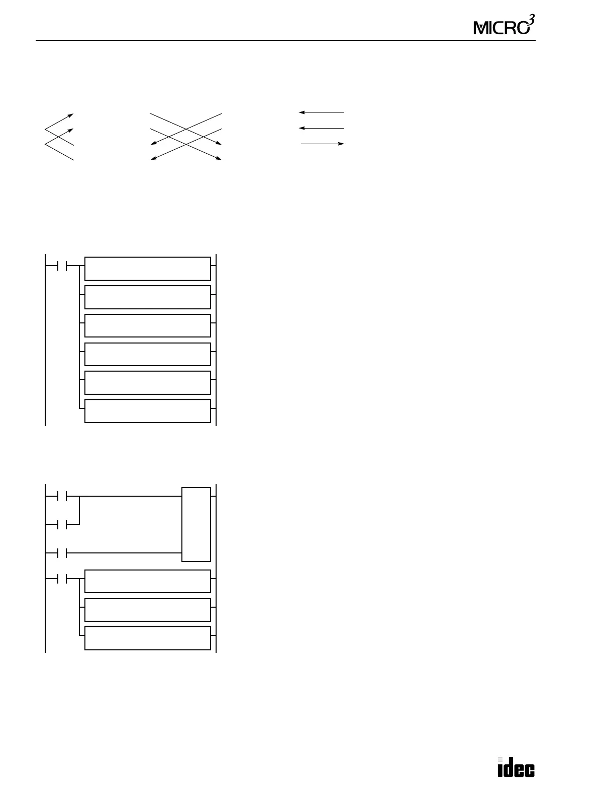
Master station program
Slave station program
The same program is used for slave stations 1 through 6 in this example.
Master Station Slave Station 1
D60 (Error Code)
D61 (Trans. H)
I0 through I7, I10 through I17
Q0 through Q7, Q10 through Q17
D62 (Trans. L)
D63 (Receive H)
D64 (Receive L)
D85 (Error Code)
D86 (Trans. H)
D87 (Trans. L)
D88 (Receive H)
D89 (Receive L)
Counter C2 current value
M317
MOV REP
2
M317 is the in-operation output special internal relay which remains on dur-
ing operation.
The first MOV (move) instruction with 2 repeat cycles sets the data of data
registers D63 and D64 (receive data H and L for slave station 1) to data reg-
isters D61 and D62 (transmission data H and L for slave station 1), respec-
tively.
Similarly, next 5 MOV instructions set data of 2 receive data registers to 2
transmission data registers for slave stations 2 through 6.
D63 and D64 → D61 and D62
D68 and D69 → D66 and D67
D73 and D74 → D71 and D72
D78 and D79 → D76 and D77
D83 and D84 → D81 and D82
D88 and D89 → D86 and D87
S1 R
D63
D1 R
D61
MOV REP
2
S1 R
D68
D1 R
D66
MOV REP
2
S1 R
D73
D1 R
D71
MOV REP
2
S1 R
D78
D1 R
D76
MOV REP
2
S1 R
D83
D1 R
D81
MOV REP
2
S1 R
D88
D1 R
D86
M301
M301 is the initialize pulse special internal relay to reset counter C2 when
starting operation.
Adding counter C2 counts input signals to input I0 and is reset when input
I1 is turned on.
M317 is the in-operation output special internal relay which remains on dur-
ing operation.
The first MOV (move) instruction sets 16 inputs I0 through I17 to data reg-
ister D86 (transmission data H).
The second MOV instruction sets the counter C2 current value to data regis-
ter D87 (transmission data L).
The last MOV instruction sets data of data register D88 (receive data H) to
16 outputs Q0 through Q17.
C2
9999
Reset
I1
I0
M317
MOV REP
**
S1
I0
D1
D86
MOV REP
**
S1
C2
D1
D87
MOV REP
**
S1
D88
D1
Q0
Pulse