4: SPECIAL FUNCTIONS
USER’S MANUAL 4-19
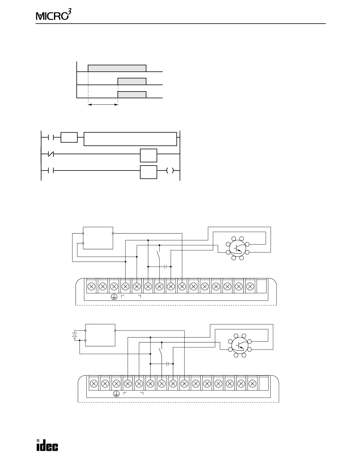
Example: ON-delay Analog Timer
This example demonstrates a program to vary the timer preset value for the TIM instruction between 0.2 and 20 sec using
the TMH instruction for measuring the output pulse OFF duration of the external analog timer unit.
Ladder Diagram
Wiring Diagram
•
When using with NPN-output sensors
•
When using with PNP-output sensors
* When using analog timer in an environment subject to noise or when using long wires for connecting the analog timer, con-
nect a capacitor of 1 µF/50V between the DC IN COM terminal and the input terminal connected to the analog timer output.
Input I0
ON
OFF
TIM1
ON
OFF
Output Q0
ON
OFF
Time delay
0.2 to 20 sec
I0: Start input for TIM1
I1: Pulse output from the external analog timer unit
Q0: Timer output
D10: Preset value for TIM1
TMH0: 10-msec timer used for measuring the OFF duration
of the pulse output from the external analog timer unit
TIM1: 100-msec instruction used for time-delay
SUB S1
9999
I1
S2
T0
D1
D10
I1
SOTU
I0
REP
**
TH0
9999
Q0
T1
D10
When the output pulse of the analog timer unit is turned
on, the timer TMH0 current value is subtracted from
9999, and the result is set to data register D10, which is
used as a preset value for 100-msec timer TIM1.
When the output pulse is off, 10-msec timer TMH0 times
down from 9999 to measure the OFF duration of the
external analog timer unit output.
When I0 is turned on timer TIM1 starts to time down
from preset value D10. When TIM1 times out, Q0 is
turned on.
54
63
72
81
NPN-output
Sensor
+
–
Output
+
Analog Timer Unit
PFA-1U11
–
*
Output
100-240V AC
LN
DC OUT
24V 0V
DC IN
COM
0123456710
–
54
63
72
81
PNP-output
Sensor
+
Output
+
Analog Timer Unit
PFA-1U11
–
*
External Power
24V DC
Output
100-240V AC
LN
DC OUT
24V 0V
DC IN
COM
0123456710