4: S
PECIAL
F
UNCTIONS
4-32 U
SER
’
S
M
ANUAL
Example: D/A Conversion
The following example demonstrates a program to control motor speed using the D/A converter unit. Analog potentiome-
ter 0 on the
MICRO
3
base unit is used to change the digital value for operand S1 (pulse width coefficient) of the PWM
(pulse width modulation) instruction. The PWM output from output Q0 is converted to an analog value by the D/A con-
verter unit and the output from the D/A converter unit is entered to the inverter to control the motor speed.
Ladder Diagram
Note:
When using the D/A converter unit, the MODE in the PWM instruction must be set to MODE3 to make sure of cor-
rect output from the D/A converter unit. When the value of the data register designated as S1 is between 0 and 4, the PWM
instruction sets operand S1 to 5, and the minimum output is generated by the D/A converter unit. If the value of the data
register designated as S1 exceeds 249 during operation, a user program execution error will occur, then error indicator
ERR1 on the
MICRO
3
base unit is lit, and special internal relay M304 is also turned on. Do not designate constant 0
through 4 as S1. If a constant value between 0 and 4 is designated as S1, then the output is not generated correctly.
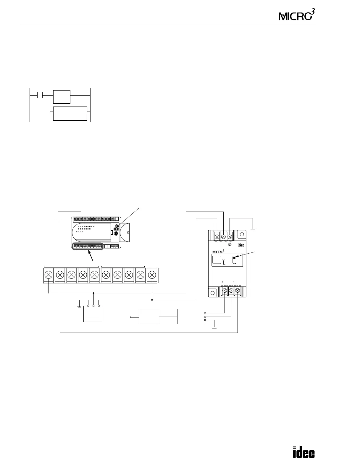
I/O Wiring Diagram
This wiring example shows a sink-output connection for the
MICRO
3
base unit.
M317
M317 is the in-operation output special internal relay.
The ANR0 (analog read 0) instruction reads the analog potentiometer 0 setting and sets dig-
ital value 0 through 249 to data register D0.
The PWM (pulse width modulation) instruction converts the D0 value to a pulse output sig-
nal of variable pulse widths.
ANR0
D0
S1
D0
PWM
MODE3
MICRO
3
Base Unit
24V DC
Power
+–FG
Set the input selector
+–
24V DC
D/A UNIT
OUTPUT
4-20mA
POWER
SCE
SINK
+–
ANALOG WIRE TO
OUT 0
OUTPUT INPUT
Ground the
FG terminal.
switch to SCE.
Inverter
+
–
FG
Motor
FC2A-C16B1
OUT
COM0(–)
0123
OUT
COM1(–)
456+V
Analog potentiometer 0
◆ For dimensions of A/D and D/A converter units, see page 1-24. ◆