4: S
PECIAL
F
UNCTIONS
U
SER
’
S
M
ANUAL
4-31
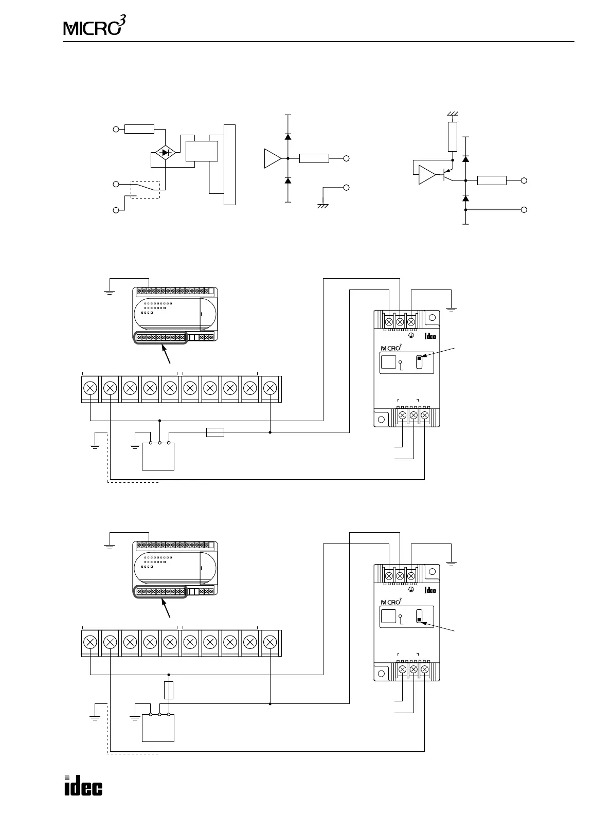
Type of Protection
• Input Circuit • Output Circuit
Wiring Diagram
• Transistor Sink Output from MICRO
3
• Transistor Protect Source Output from MICRO
3
ANALOG
+V
–V
–24V DC
INPUT
+24V DC
(GND)
SINK
SCE
Internal Circuit
The input selector switch is used to
select sink or source input.
1.5kΩ
Photo
Isolator
4.7kΩ
OUTPUT +
ANALOG
OUTPUT –
ANALOG
+V
–V
4.7kΩ
OUTPUT +
ANALOG
OUTPUT –
Voltage Output Current Output
24V DC
Power
+–FG
Set the input selector
Analog
Shield Wire
+–
24V DC
D/A UNIT
OUTPUT
4-20mA
POWER
SCE
SINK
+–
ANALOG WIRE TO
OUT 0
OUTPUT INPUT
Ground the
FG terminal.
switch to SCE.
Output
OUT
COM0(–)
0123
OUT
COM1(–)
456+V
When using a transistor
sink output type MICRO
3
base unit, select the
source input to the D/A
converter unit.
1A Fuse
24V DC
Power
+–FG
Set the input selector
Analog
Shield Wire
+–
24V DC
D/A UNIT
OUTPUT
4-20mA
POWER
SCE
SINK
+–
ANALOG WIRE TO
OUT 0
OUTPUT INPUT
Ground the
FG terminal.
switch to SINK.
Output
OUT
COM0(+)
0123
OUT
COM1(+)
456–V
When using a transistor
protect source output
type
MICRO
3
base unit,
select the sink input to
the D/A converter unit.
1A Fuse