4: SPECIAL FUNCTIONS
4-30 USER’S MANUAL
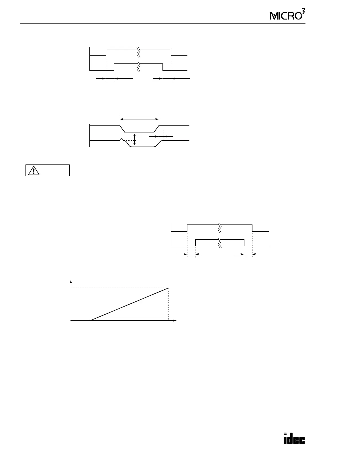
Power Supply Timing Chart
Output Response at Power Up and Down
Resolution
D/A Converter Power
ON
OFF
≥ 0 sec
MICRO
3
Main Power
ON
OFF
≥ 0 sec
Power up the D/A converter unit and MICRO
3
at the same time, or power up the MICRO
3
first.
Power down the D/A converter unit and
MICRO
3
at the same time, or power down the
D/A converter first.
D/A Converter Output
ON
OFF
A
MICRO
3
Main Power
ON
OFF
≥ 1 sec
B
A ≤ 1% of full scale
B ≤ 1 sec
Caution
D/A converter units FC2A-DA3 and FC2A-DA5 generate a momentary voltage output when the
MICRO
3
or the D/A converter unit is powered up or when the MICRO
3
is started or stopped.
• FC2A-DA3: –5V DC
• FC2A-DA5: –10V DC
When the analog voltage output from the FC2A-DA3 or FC2A-DA5 is used to control motor and
a trouble may occur, use a relay to ensure a delay between the RUN/STOP signal and the analog
output as shown below.
Analog Output Control Relay
ON
OFF
≥ 1 sec
RUN/STOP
ON
OFF
≥ 1 sec
PWM operand S1
0 249
Minimum Output
Maximum Output
245 increments
When the value of the data register designated as
operand S1 (pulse width coefficient) for the PWM
(pulse width modulation) instruction is between 0
and 4, S1 is designated as 5, and the minimum out-
put is generated.
Do not designate constant 0 through 4 as S1. If a
constant value between 0 and 4 is designated as S1,
the output is not generated correctly.
5
Analog
Output
Value Maximum Output Minimum Output–
()
S1 5–
244
---------------
×
Minimum Output+=