4: SPECIAL FUNCTIONS
USER’S MANUAL 4-29
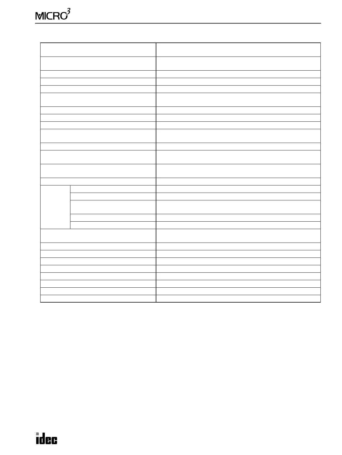
Function Specifications (D/A Converter Unit)
Load Impedance in Signal Range
Voltage output unit: 5 kΩ minimum
Current output unit: 250Ω (300Ω maximum)
Analog Output Error
Maximum error at 25°C: ±0.7% of full scale
Temperature coefficient: –0.005% of full scale/°C (typ.)
Maximum Error over Full Temperature Range ±1% of full scale
Digital Resolution 245 increments
Data Format in User Program BCD (0 to 249)
Value of LSB (Least Significant Bit)
FC2A-DA1 FC2A-DA2 FC2A-DA3 FC2A-DA4 FC2A-DA5
41 mV 65 µA 20 mV 41 mV 82 mV
Total Output System Transfer Time 1 msec maximum
Settling Time after Maximum Range Change 0.5 sec maximum after changing from 0% to 95%
Overshoot 0%
Maximum Temporary Deviation during
Electrical Noise Tests and Test Conditions
3% maximum of full scale at impulse test 500V
Output Short-circuit No damage (between OUTPUT + and –)
Maximum Allowed Output Voltage
Voltage output type: ±12V DC (between OUTPUT + and –)
Current output type: +12 or –0.6V DC (between OUTPUT + and –)
Maximum Allowed Input Voltage
Between INPUT and GND: +30V DC
Between INPUT and +24V: –30V DC
Output Voltage Drop 1% maximum of full scale
External
Power
Supply
Data
Rated Power Voltage 24V DC
Power Voltage Range 19 to 30V DC
Resetting Method
Use a power supply of self-reset type or with an overcurrent protection
against 10A inrush current into the D/A converter unit
Inrush Current 10A
Output Power 2.5W minimum
Calibration or Verification to Maintain Rated
Accuracy
Once every 6 months (recommended value)
Type of Applicable Load Resistive load (5 kΩ minimum, voltage output type)
Effect of Improper Output Terminal Connection Permanent damage may be caused
Monotonicity Yes
Crosstalk No crosstalk because of 1 channel output
Non-linearity 0.2% maximum of full scale
Repeatability after Stabilization Time 0.5% maximum of full scale (more than 30 minutes after power up)
Output Ripple 1% maximum of full scale
MICRO
3
Setting PWM MODE3