4: SPECIAL FUNCTIONS
4-28 USER’S MANUAL
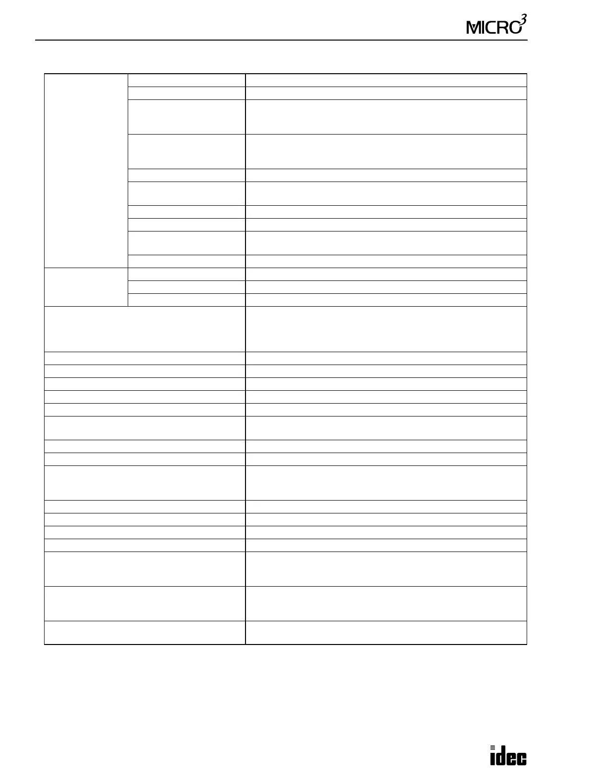
General Specifications (D/A Converter Unit)
Power Supply
Rated Power Voltage 24V DC
Allowable Voltage Range 19 to 30V DC (including ripple)
Dielectric Strength
Between input and output terminals: 500V AC
Between I/O terminal and FG: 1500V AC
Between power and output terminals: Not isolated
Insulation Resistance
(500V DC megger)
Between input and output terminals: 10 M Ω minimum
Between I/O terminal and FG: 10 M Ω minimum
Between power and output terminals: Not isolated
Power Consumption Approx. 2.5W (24V DC)
Allowable Momentary
Power Interruption
25 msec minimum (24V DC)
Power Inrush Current 10A maximum
Ground Grounding resistance: 100 Ω maximum
Protective Ground
Allowable Current
10A maximum, 10 sec
Grounding Wire 1.25 mm
2
(AWG16)
Effect of Improper
Power Supply
Connection
Reverse Polarity No operation, no damage
Improper Voltage Level Permanent damage may be caused
Improper Lead Connection Connection failure may be caused
Power Up/Down Order
Power up the D/A converter unit and MICRO
3
at the same time, or
power up the MICRO
3
first.
Power down the D/A converter unit and MICRO
3
at the same time, or
power down the D/A converter first.
Operating Temperature 0 to 60°C
Storage Temperature –25 to +70°C
Relative Humidity Relative humidity severity level RH1, 30 to 95% (non-condensing)
Pollution Degree 2 (IEC 664)
Corrosion Immunity Free from corrosive gases
Altitude
Operation: 0 to 2,000m (0 to 6,565 feet)
Transport: 0 to 3,000m (0 to 9,840 feet)
Vibration Resistance (IEC 68-2-6) 5 to 55Hz, 60 m/sec
2
, 2 hours each in 3 axes
Shock Resistance (IEC 62-2-7) 300 m/sec
2
, 11 msec, 3 shocks each in 3 axes
Wiring
Core wire 0.75 to 1.25 mm
2
(AWG18 to AWG16)
Input lines must be separated from power, output, and motor lines.
M3 screw terminal with finger protection cover
Input Wiring Length 2m (6.56 feet) maximum using shielded wire
Output Wiring Length 50m (164 feet) maximum using 2-core shielded wire
Dimensions 45W × 80H × 70D mm (1.772"W × 3.150"H × 2.756"D)
Weight Approx. 120g
Standards
EN61131-1, EN61131-2, EN60204-1
PrEN50082-2, EN55011
UL 508, CSA C22.2 No. 142
Certification File No.
TÜV Product Service E9 95 09 13332 313
UL E102542
CSA LR66809
Others (IEC 1131-2 Information)
IEC1131-2 3.4.2.2.3 8) No common point because of 1 channel
input