SV-DA200 series AC servo drive Function codes
-160-
This parameter is used to set the condition of mixed control deviation clearing. After rotating for the
set circles, the mixed control deviation will be cleared. If it is set to 0, the deviation will not be
cleared.
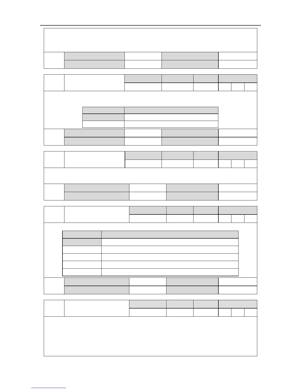
External grating pulse
output mode of AB phase
It is used to set the signal source of pulse feedback output when fully-closed loop function is
enabled under position mode.
Pulse feedback signal source
External linear encoder
(2
nd
encoder) resolution
Set the resolution of external linear encoder (2
nd
encoder). When connecting 2
nd
encoder, output
the number of pulses per circle.
Frequency division output
source
Set the signal source of frequency division output.
Pulse feedback signal source
Normal frequency-division output
AB quadrature pulse input bypass
The 1
st
encoder bypass (valid only for incremental encoder)
External linear encoder (2
nd
encoder) Z signal type
As Z signal width is divided into 1/4, 1/2 and 1/1, the starting phase of the signal for each width
corresponds to 4 kinds of AB level, so there are in total 12 kinds of combinations, however, in
order to adapt to these combinations and ensure the capture value is normal in both forward and
reverse direction, it is necessary to set the AB state value corresponds to the middle of Z signal
high level. For 1/4 and 1/2, they require any one of AB states during high level period after Z type

 Loading...
