SV-DA200 series AC servo drive Control mode applications
-57-
If the digital input is valid, the drive will report Er10-3 and stop.
This function is the control signal of inertia ratio switching between 1
st
inertia ratio and 2
nd
inertia ratio.
When the digital input is valid, the internal software uses P1.02; and when invalid, use P1.01.
This function is the control signal of emergency stop.
If P3.41 is set to 0 and when the digital input is valid, the drive will stop to report Er10-4.
This function is the input signal of HOME SWITCH.
When the drive carries out HOME action, in some HOME mode, if the digital input is detected to
be valid, HOME is finished. Refer to P5.10 for information.
This function is the trigger control signal of HOME function, and the rising edge is valid.
The digital input function has the same function with P5.15.
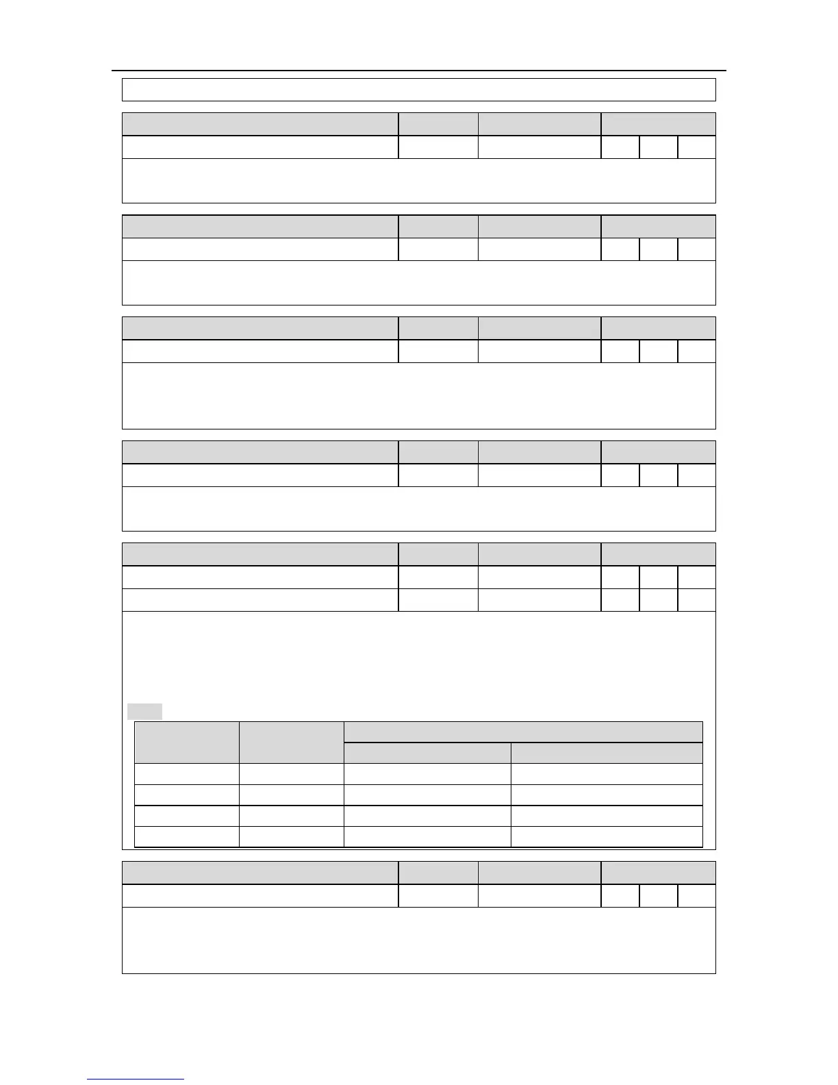
Molecule 1 of electric gear ratio
Molecule 2 of electric gear ratio
The function is the selection signal of the electric gear ratio, up to 4 groups of electric gears can
be switched.
Before using the function, it is necessary to set P0.22 to 0 and then set different electric gear ratio
(P0.25–P0.29).
Note: If the electric gear is switched by digital value, it is necessary to set P4.10 to 0.
In the PTP control mode, it needs to be used with internal position command 1–4.
During using, select the target step by the internal position command selection 1–4, and then
trigger the switching action selected by target step via the rising edging of this digital value.

 Loading...
