SV-DA200 series AC servo drive Control mode applications
-71-
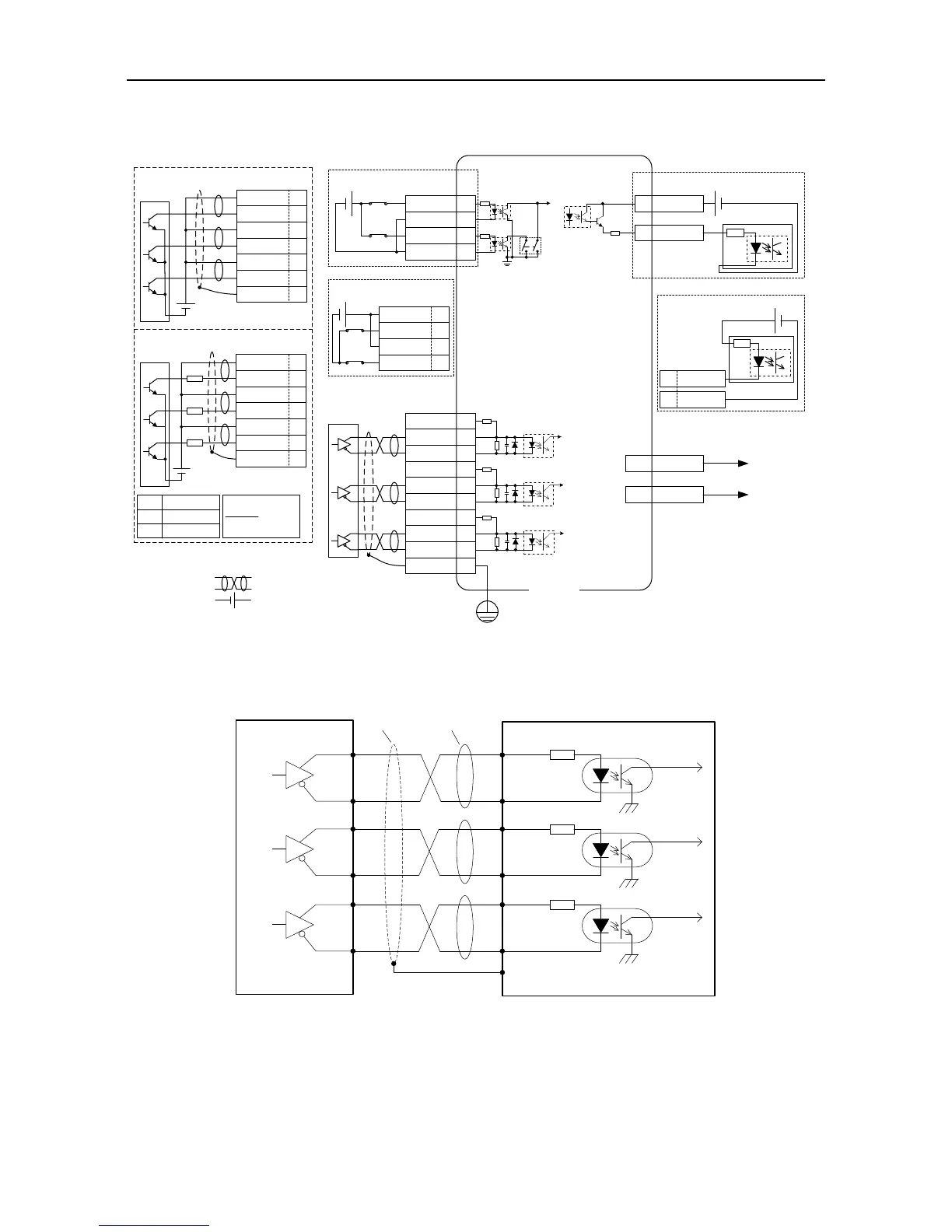
4.6.2 CN5 wiring diagram of medium power range (7.5kW–55kW)
2
nd
encoder and STO
Differential command pulse input
(Max 4Mpps)
EXA+ 1
EXA- 2
OC_EXA 19
2kΩ
EXB+ 3
EXB- 4
OC_EXB 18
2kΩ
OC_EXZ 17
24V power, built-in current limit resistor
12~24V power, connects to external
current limit resistor
V
DC
12~24V
V
DC
24V
R
R
V
DC
-1.5
R+68
10mA
Note: The max input of open collector is 200kpps
12V 1k,1/4W
24V 2k,1/3W
EXZ+ 5
13 EDM+
14 EDM-
- +
EXZ- 6
FG
HWBB1+ 11
HWBB1- 12
HWBB2+ 15
HWBB2- 16
2kΩ
OC_EXZ 17
EXZ- 6
EXB- 4
OC_EXB 18
EXA- 2
OC_EXA 19
FG
EXA+ 1
EXA- 2
EXB+ 3
EXB- 4
EXZ+ 5
EXZ- 6
R
FG
When S1 is set to ON, safety
input terminal signal is
invalid, servo can work
normally; when S1 set to
OFF, the servo can work
normally only when safety
input terminal signal is valid.
- +
HWBB1+ 11
HWBB1- 12
HWBB2+ 15
HWBB2- 16
S1: STO switch
7/9 EX5V
8/10 EX0V
EX0V
EX5V
Safety terminal signal is active-low
Safety terminal signal is active-high
+ -
Safety output signal is active-high
Safety output signal is active-low
13 EDM+
14 EDM-
+ -
CN5
+
-
+
-
Note: 1. ( ) is shielded twisted pair;
2. ( ) is power source, DC12~24V which
is prepared by the user.
V
DC
R parameter
Differential pulse input signal voltage is ±5V, max frequency is 4MHz;
Such signal transmission mode has optimal anti-noise capacity, it is recommended to take this
connection mode as priority.
Connection mode 2: Open collector mode 1

 Loading...
