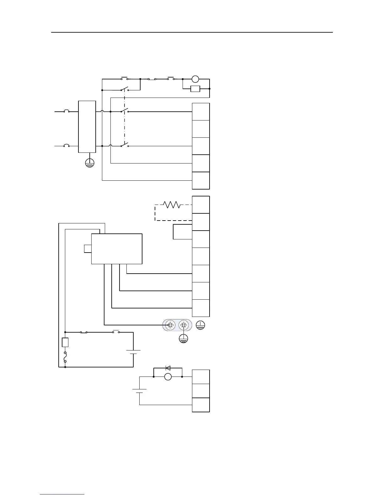
· Do not disconnect the short
connection cable between B2 and
B3, unless external regenerative
brake resistor is used;
· When external regenerative brake
resistor is used, disconnect the short
connection cable between B2 and
B3 and make connection based on
the dotted lines in the diagram.
· Connect output U, V and W to the
drive according to the motor cable
phase sequence of servo motor,
wrong phase sequence will cause
drive fault
· Be sure to ground the servo drive to
avoid accident of electrical shock.
· The electromagnetic brake uses 24V
power supply which should be
provided by the user. Moreover, it
must be isolated from the DC12-24V
power supply which is used by the
control signal.
· Pay attention to the connection of
the freewheeling diode. Reversed
polarity may damage the drive.
· The user is required to make this
emergency stop protection circuit.
· Add surge absorbing devices on
both ends of the electromagnetic
contactor winding.
· The power input voltage range:
AC 220V(-15%)~240V(+10%)
· Connect main circuit to terminal L1
and terminal L3.
· Note: Please use 3-phase input
power for the drive of 1.5kW and
above.
Yellow/Green
Surge absorber
Fuse
Breaker
MC
MC
ALM
CN1
Emergency
stop button
RY
EMI
filter
DC 12~24V
(±10%)
DC 24V
(±10%)
OFF
ALM
ON
+
-
+
-
Motor
L1
L2
L3
L1C
L2C
B3
+
B2
U
V
W
-
COM-
ALM

 Loading...
