SV-DA200 series AC servo drive Running and operation
-80-
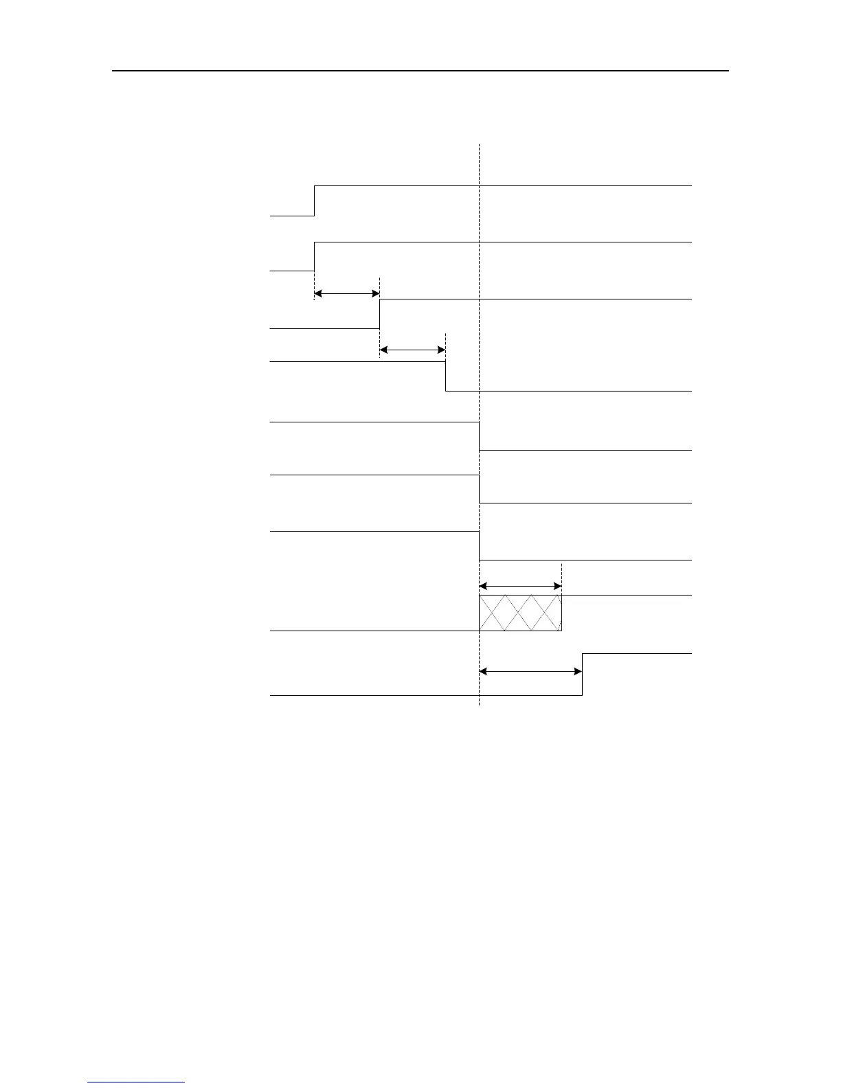
5.1.9 Sequence diagram
5.1.9.1 Sequence diagram of power-on and servo ON
Main power
Control power
PWM output
Electromagnetic
brake release signal
output (BRK)
Servo enable
(SON)
Microprocessor state
Note 1: The delay time from the completion of microprocessor initialization to the readiness of servo output
can be set via P4.54;
Note 2: The condition for the RDY output signal electric leveL to become low is: servo has no fault and main
circuit DC voltage has been established (voltage is higher than 250V/430V (220V series/400V series));
when the main circuit DC voltage is less than 170V/310V (220V series/400V series), Er13-1 alarm will
occur. The time interval from the readiness of servo and enabling of servo can be controlled by users;
Note 3: The servo enable signal can become valid only when RDY output signal is valid;
Note 4: The actual electric level corresponding to the IO valid state can be set via P3.00~P3.15.
Position/speed/torque
command input
About 1.2s
Note 3
100ms
Control circuit power-on
Main circuit power-on
Program starts running
Servo has no output
Motor brake releaseMotor brake
Servo has output
Command input invalid Command input valid
Fan signal
Fan operating
Fan does not operate
Power-on process Servo On process
100ms
Program initialization
Servo ready state
(RDY)
Note 2
Note 1
Invalid
Invalid
Valid
Valid
Note 4
Brake is
releasing

 Loading...
