GENERAL
The implement pump has four positive displacement
gear pump sections. Pump sections are numbered
from the shaft end. Pump section 1 supplies oil to the
right wing mower. Pump section 2 supplies oil to the
left wing mower. Pump section 3 supplies oil to the
front mower. Pump section 4 supplies oil for steering,
lift and lower, charge oil for the traction pump, differ-
ential lock and the 4 wheel drive valve.
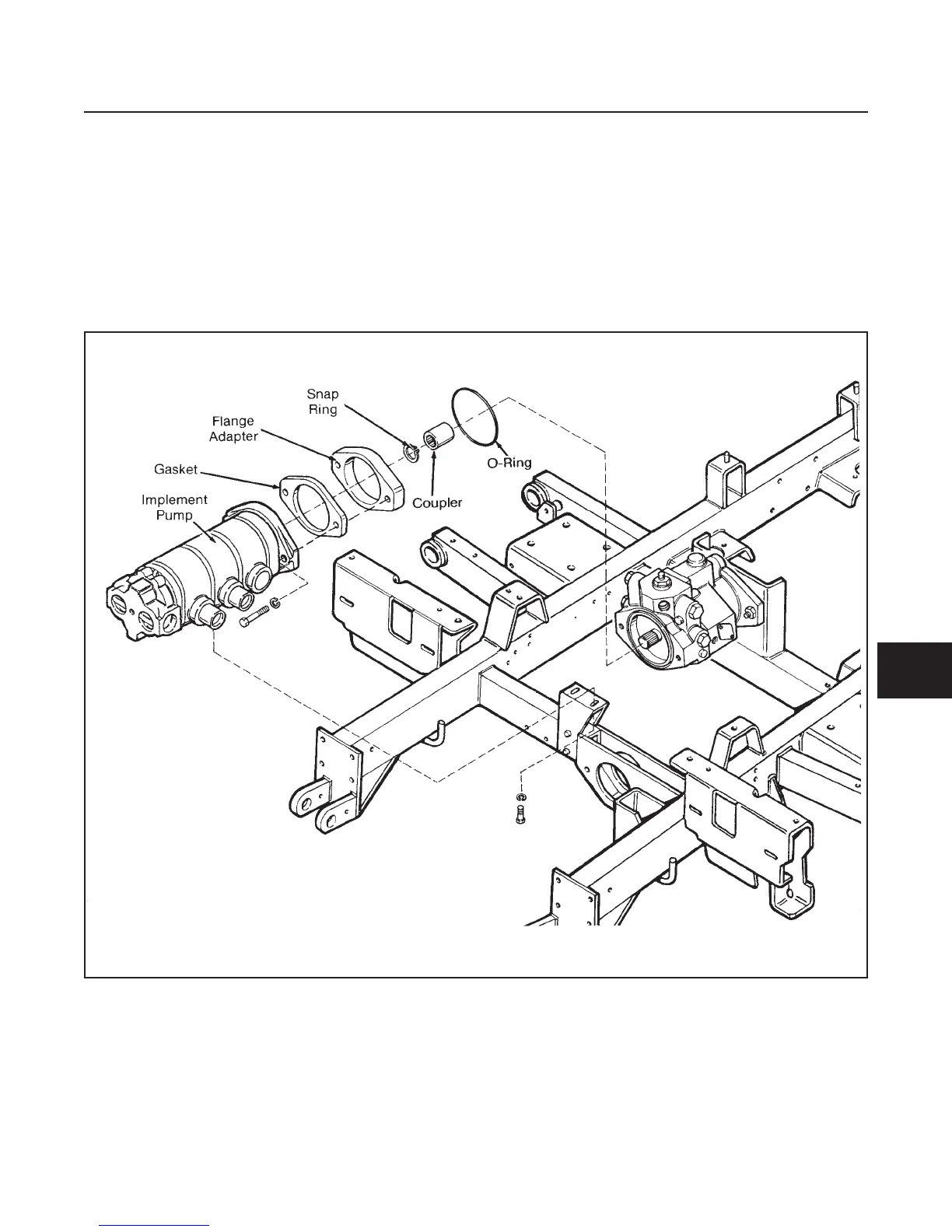
REMOVAL (See Figure 8E-1)
1. Using a suitable solution, clean the pump and sur-
rounding area.
2. Tag and mark the location of hydraulic lines.
3. Remove hydraulic lines.
4. Remove pump mounting hardware and remove
pump from tractor.
5. Plug all hydraulic lines and pump ports.
HYDRAULICS
SECTION 8E. IMPLEMENT PUMP
8E-1
8E
Figure 8E-1. Implement Pump Removal
 Loading...


